Difference between revisions of "CobraPin"
Tfulenwider (talk | contribs) (→Overview) |
Tfulenwider (talk | contribs) |
||
| Line 24: | Line 24: | ||
[[File:CobraPinConnectionDiagram.jpg]] | [[File:CobraPinConnectionDiagram.jpg]] | ||
===Power=== | ===Power=== | ||
| + | Power comes in to the board on two 4-pin 3.96mm pitch connectors. The default connectors are JST VH style. The pinout is labelled in silkscreen on the board. | ||
| + | |||
| + | '''J9''': Solenoid power input (24-50V) | ||
| + | |||
| + | '''J10''': Neopixel 5V input | ||
===Coil Ouputs=== | ===Coil Ouputs=== | ||
| + | The 24 solenoids are broken up into 3 banks of 8 outputs. The 3 9-pin 3.96mm connectors are JST VH style. There is a ninth pin on the connector that can be used as a key. That pin is marked by an asterisk in silkscreen. The solenoid outputs are labeled in silkscreen with the MPF compatible numbers. | ||
| + | |||
| + | Each solenoid has a diode to help protect the transistor. You may still use coils with axial diodes installed, but you MUST ensure that you connect them with the correct polarity. | ||
| + | |||
| + | '''J6''': Solenoid bank A outputs | ||
| + | |||
| + | '''J7''': Solenoid bank B outputs | ||
| + | |||
| + | '''J8''': Solenoid bank C outputs | ||
| + | |||
| + | Each bank has an LED next to it to indicate if that bank has power. Check these if you are concerned you have blown a fuse. | ||
| + | |||
| + | Each solenoid has an associated yellow LED to indicate it is being driven by the processor. It is highly recommended to test a new setup '''''without''''' high voltage power or without the coils plugged in. Using these LEDs, you can verify that each output is being driven correctly. | ||
===Switch Inputs=== | ===Switch Inputs=== | ||
===Neopixel RGB LEDs=== | ===Neopixel RGB LEDs=== | ||
Revision as of 18:39, 11 January 2021
Contents
CobraPin Pinball Controller
This page is under construction
Overview
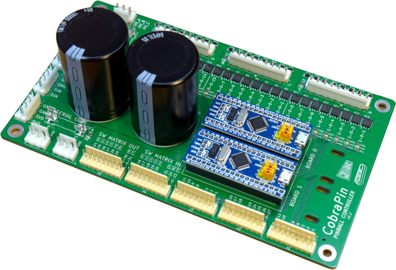
CobraPin is a pinball controller designed to offer a basic all-in-one assembled affordable solution. It is intended to be hosted by a computer running the Mission Pinball Framework (MPF) and is based on the Open Pinball Project (OPP) It will be released to the public in 2021 on Kickstarter.
Features:
- 24 coil drivers for solenoids, flashers, motors, etc. Outputs are broken out into 3 banks of 8 outputs.
- 38 direct switch inputs <OR> 22 direct inputs and an 8x8 switch matrix
- Neopixel support for 512 RGB or RGBW LEDs
- 24-50V power filter. Board also provides the common ground for the supplies.
- Fuses for solenoid banks and Neopixels
- Easy replacement of at-risk components
- Processor boards are socketed
- Transistors can be removed with simple soldering tools and replaced with through-hole components
- Fuse clips for common 5x20mm fuses
Expansion Board
An expansion board for CobraPin is planned, but not yet complete. It should support a lamp matrix, 8 additional coil outputs, and 8 additional direct inputs. The purpose of the expansion board is to make it easier for people to control existing machines with flashers and matrix controlled lamps
Wiring
Power
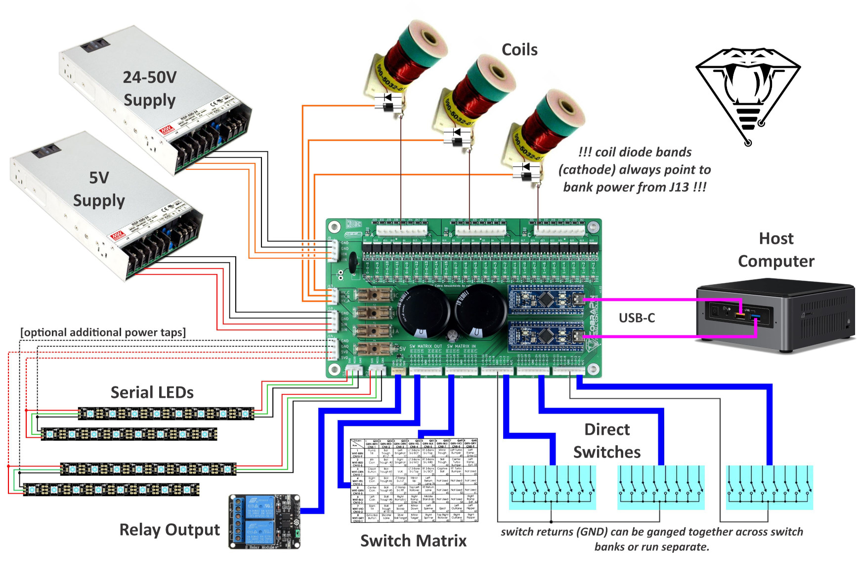
Power comes in to the board on two 4-pin 3.96mm pitch connectors. The default connectors are JST VH style. The pinout is labelled in silkscreen on the board.
J9: Solenoid power input (24-50V)
J10: Neopixel 5V input
Coil Ouputs
The 24 solenoids are broken up into 3 banks of 8 outputs. The 3 9-pin 3.96mm connectors are JST VH style. There is a ninth pin on the connector that can be used as a key. That pin is marked by an asterisk in silkscreen. The solenoid outputs are labeled in silkscreen with the MPF compatible numbers.
Each solenoid has a diode to help protect the transistor. You may still use coils with axial diodes installed, but you MUST ensure that you connect them with the correct polarity.
J6: Solenoid bank A outputs
J7: Solenoid bank B outputs
J8: Solenoid bank C outputs
Each bank has an LED next to it to indicate if that bank has power. Check these if you are concerned you have blown a fuse.
Each solenoid has an associated yellow LED to indicate it is being driven by the processor. It is highly recommended to test a new setup without high voltage power or without the coils plugged in. Using these LEDs, you can verify that each output is being driven correctly.
Switch Inputs
Neopixel RGB LEDs
MPF Configuration
It is HIGHLY RECOMMENDED that you start your MPF game-making journey with the MPF Tutorial
For detailed MPF documentation, head over to MPF Docs
CobraPin specific info can be found here: CobraPin on MPF Docs
STM32 Programming and OPP Configuration
The firmware on the STM32 board exists in two parts: the base application and the OPP configuration. As delivered, the boards should be programmed and configured appropriately. But if you need to updated something or replace a processor board, this section is for you. The base application must be programmed with a separate programming device while the OPP configuration can be changed over USB via Python scripts.


