Difference between revisions of "Basics"
(→Direct versus Serial) |
m (→Direct Wired LEDs) |
||
| (20 intermediate revisions by 2 users not shown) | |||
| Line 66: | Line 66: | ||
It shows a number of different devices but the key connections are between the high current power supply, the board, and the coils, showing how the ''negative'' lead of the power supply goes to the board, while the ''positive'' goes directly to the coil. | It shows a number of different devices but the key connections are between the high current power supply, the board, and the coils, showing how the ''negative'' lead of the power supply goes to the board, while the ''positive'' goes directly to the coil. | ||
| − | For ''P-ROC'', the connection method is slightly different, in that voltages and ground are connected from the board instead of from the power supplies separately, as per this diagram. | + | For ''P-ROC/P3-ROC'', the connection method is slightly different, in that voltages and ground are connected from the board instead of from the power supplies separately, as per this diagram. |
[[File:pd16-diagram.png|PD-16 wiring diagram]] | [[File:pd16-diagram.png|PD-16 wiring diagram]] | ||
| Line 74: | Line 74: | ||
Depending on your controller, you may or may not need a '''Diode''' connecting the two leads on your coils. The reason for this diode is that when a coil's magnetic field collapses when power is stopped, it produces an in-rush of current in the opposite direction - a '''Flyback''' voltage. The diode is there to shunt that back into the coil to avoid damaging the transistors. | Depending on your controller, you may or may not need a '''Diode''' connecting the two leads on your coils. The reason for this diode is that when a coil's magnetic field collapses when power is stopped, it produces an in-rush of current in the opposite direction - a '''Flyback''' voltage. The diode is there to shunt that back into the coil to avoid damaging the transistors. | ||
| − | ''P-ROC'' and ''FAST'' controllers do not need them as they have built-in flyback protection, while ''OPP'' and other original manufacturer boards do require external diodes. Make sure to confirm the need for diodes prior to wiring a game. | + | ''P-ROC/P3-ROC'' and ''FAST'' controllers do not need them as they have built-in flyback protection, while ''OPP'' and other original manufacturer boards do require external diodes. Make sure to confirm the need for diodes prior to wiring a game. |
=== Lamps === | === Lamps === | ||
| Line 82: | Line 82: | ||
==== Direct Wired LEDs ==== | ==== Direct Wired LEDs ==== | ||
| − | ''Direct wired'' LEDs are driven individually. The [https://www.multimorphic.com/store/circuit-boards/pd-led PD-LED] | + | ''Direct wired'' LEDs are driven individually. The [https://www.multimorphic.com/store/circuit-boards/pd-led PD-LED] can drive up to 84 single color LEDs or 28 RGB LEDs, for example. |
| − | The below diagram shows how to connect | + | The below diagram shows how to connect a single LED to the PD-LED. |
[[File:pw-led-hookup.png|PD-LED Connection Example]] | [[File:pw-led-hookup.png|PD-LED Connection Example]] | ||
| + | |||
| + | There are a number of options for under playfield mounting of LEDs, such as the [https://www.multimorphic.com/store/circuit-boards/rgb-led/ Multimorphic RGB LED board] or the [https://www.pinballlife.com/p3-roc-single-rgb-insert-led-pcb-assembly.html Pinball Life RGB LED]. | ||
| + | |||
| + | [[File:multi-led-board.png|Multimorphic RGB LED]] [[File:pbl-led-board.jpg|Pinball Life RGB LED]] | ||
==== Serial Chain LEDs ==== | ==== Serial Chain LEDs ==== | ||
| Line 95: | Line 99: | ||
''Serial Chain'' LEDs are LEDs that are daisy-chained together and use a serial protocol to accept commands to light up and are usually full colour '''RGB''' (red/green/blue). This means they can be programmed to light any colour. | ''Serial Chain'' LEDs are LEDs that are daisy-chained together and use a serial protocol to accept commands to light up and are usually full colour '''RGB''' (red/green/blue). This means they can be programmed to light any colour. | ||
| − | They | + | They come in a variety of styles. |
| + | |||
| + | {| class="wikitable" | ||
| + | |- | ||
| + | ! Part Number !! Number of Pins !! Power | ||
| + | |- | ||
| + | | [https://www.espruino.com/datasheets/WS2801.pdf WS2801] || 4 wires (ground, power, clock, data) || 3.3V-5V | ||
| + | |- | ||
| + | | [https://www.adafruit.com/product/306 LPD8806] || 4 wires (ground, power, clock, data) || 3.3V-5.1V | ||
| + | |- | ||
| + | | [http://www.seeedstudio.com/document/pdf/WS2812B%20Datasheet.pdf WS2812B] || 3 wires (ground, power, data) || 3.1V-5.2V | ||
| + | |} | ||
| + | |||
| + | Very simply, you send commands via the '''Serial Protocol''' to say ''"Lamp 5, turn Red"'', and the command is sent down the line until the fifth lamp sees it and turns red. | ||
[[File:daisy-chain-led.jpg|Example of a daisy-chained LED string]] | [[File:daisy-chain-led.jpg|Example of a daisy-chained LED string]] | ||
| Line 109: | Line 126: | ||
| − | For this reason, it's recommended to use direct LEDs ''under'' the playfield, while you can use limited strings of serial LEDs ''above'' the playfield. | + | For this reason, it's recommended to use direct LEDs ''under'' the playfield, while you can use limited strings of serial LEDs ''above'' the playfield. |
| + | |||
| + | The [https://www.multimorphic.com/store/circuit-boards/pd-led/ PD-LED] can also drive ''both'' types of LEDs: '''Connector J8''' is designated for serial LEDs specifically and can drive up to '''six LED chains'''. | ||
[[File:fadecandy.png|FadeCandy from AdaFruit]] | [[File:fadecandy.png|FadeCandy from AdaFruit]] | ||
| − | One option for controlling serial LEDs is the [https://www.adafruit.com/product/1689 FadeCandy], which can control up to '''eight LED chains''' (with 64 LEDs each | + | One option for controlling serial LEDs is the [https://www.adafruit.com/product/1689 FadeCandy], which can control up to '''eight LED chains''' (with 64 LEDs each for a total of 512 LEDs) via the USB interface and is natively supported by [https://missionpinball.org/ MPF]. It can update them at up to 400Hz and provides temporal dithering and smooth hardware fades. |
| + | |||
| + | == Switches == | ||
| + | |||
| + | [[Image:Microswitch.jpg|Standard Microswitch]] | ||
| + | |||
| + | Switches come in a variety of [http://pinballmakers.com/wiki/index.php/Construction#Switch_Types types] but the most common is the '''Microswitch'''. They come in a variety of sizes and newton force values (ie. easier or harder to activate). Pinball Life sells a [https://www.pinballlife.com/index.php?p=product&id=4624 generic rollover] that covers most uses, although there are a number of different arm and mounting configurations possible. | ||
| + | |||
| + | Wiring of switches is generally '''normally open''' with '''ground sink'''. The switch is wired to ground on one side and the controller board on the other, and when pressed, it connects ground to the controller, registering as '''closed'''. | ||
| + | |||
| + | Below is an example of the wiring for switches with ''Open Pinball Project''. | ||
| − | + | [[Image:Switch-wiring.png|OPP Switch Wiring]] | |
Latest revision as of 23:42, 23 August 2023
Pinball Makers is focused primarily on providing practical, real world information for the creation of pinball machines from scratch, but there is a large segment of people who are interested in building a game but do not have experience with the basic components involved inside a pinball. This section is meant to help those people understand the basics of what makes up a pinball machine in terms of the mechanical parts and electronics.
Contents
Mechanical
Although every pinball machine is different, the basic principle is that a steel ball rolls on a wooden surface, interacting with switches and mechanical devices that either passive (such as rubber bumpers) or active (flippers, slingshots), and information is passed to the player via lights and displays. Ultimately, most pinball mechanisms can be broken down into three devices: Coils (or solenoids), Lamps (incandescent or LED) and Switches. Additionally, there are Electromagnets and Motors but they are related to coils since they all use magnetism as their motive force.
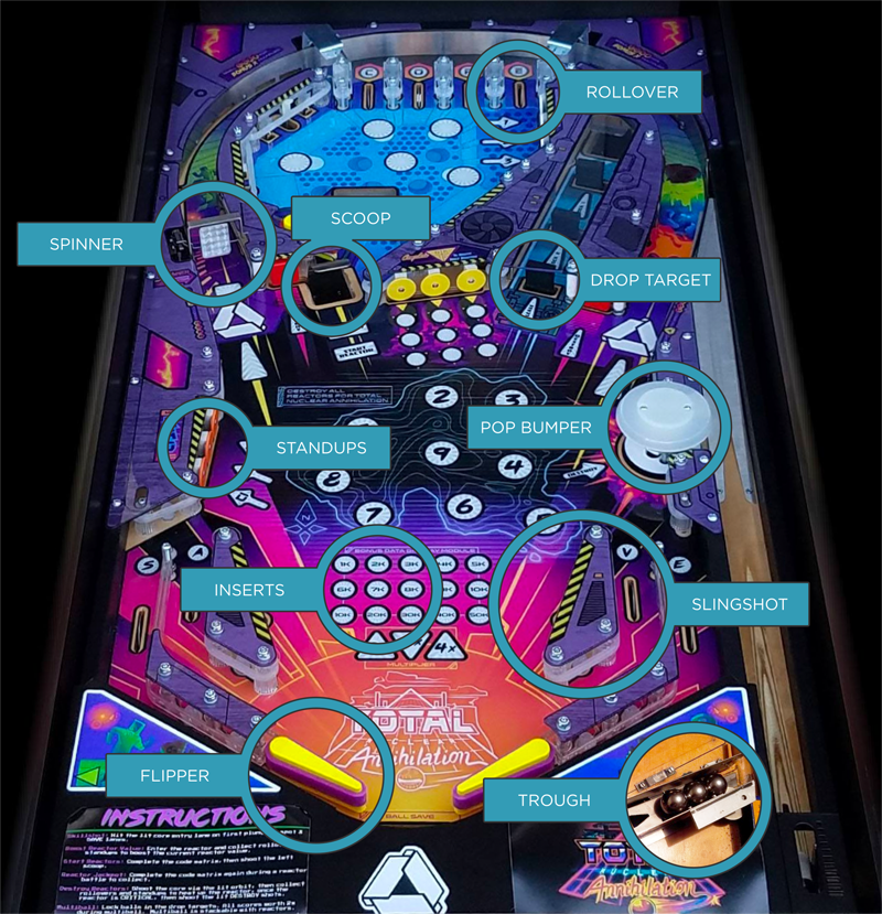
Here is a diagram showing some of the devices you will find in most pinball machines.
Mechanism Types
From the top:
- Rollover: A switch located on the underside of the playfield that is triggered when a ball rolls over it. They can be slot switches, or star rollovers, or even inductive switches you cannot see from the topside.
- Spinner: The ball hitting the flat part of the spinner causes it to spin in place, activating a switch for each turn.
- Scoop: A ball enters from the top of the playfield to under the playfield. At that point it may enter a Subway and travel to a different part of the playfield, or it may simply rest in place to be ejected back out, similar to a Saucer.
- Drop Target: When hit by the ball, it drops down into the playfield so that it cannot be hit again, usually exposing other targets or ball paths behind. They come in singles, banks of multiples, and can sometimes be computer controlled to drop without player interaction.
- Standups: These are switches that sit above the playfield and are activated by the ball.
- Pop Bumper: A device that detects a ball nearby via the plastic ring on the bottom that fires a coil and drops a ring to propel the ball in the opposite direction.
- Inserts: Clear or coloured plastic disks or other shapes that have lights - either incandescent or LED - underneath that are controlled by the game electronics.
- Slingshot: A mechanism comprising one or two standup switches (without plastic shields) and a kicker mechanism that when activated by the ball, kicks out in a single direction.
- Flipper: A player controlled bat that propels the ball in multiple directions.
- Trough: The storage tray that holds all the balls used in the game that receives the ball and serves it to the shooter lane as needed.
Electrical
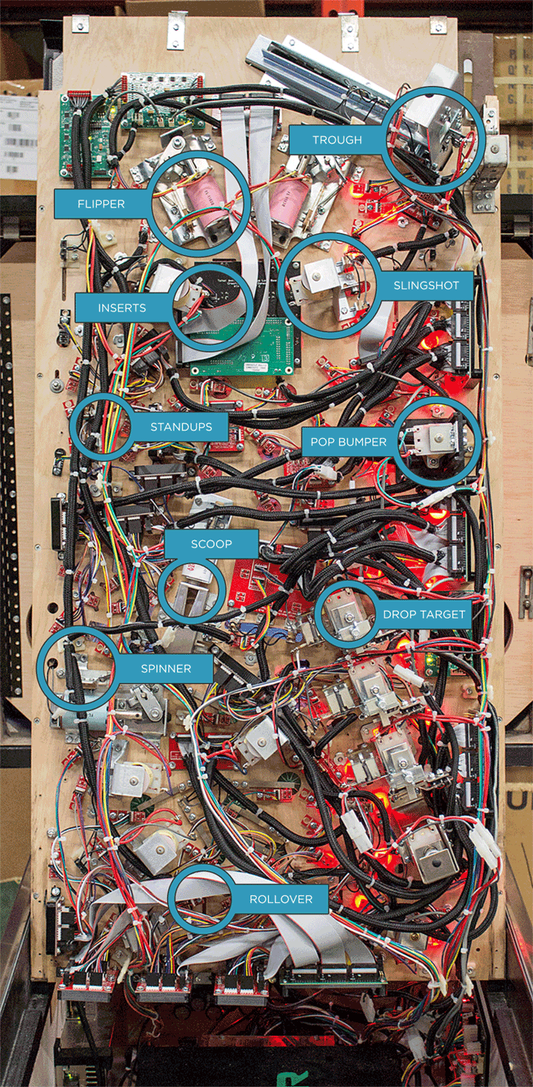
With the mechanisms covered, there needs to be a way to connect them all together and control them. That is where the electrical wiring and circuit boards come in. The following is a diagram of the underside of the same playfield in the diagram above with all the same mechanisms highlighted.
Looking at the photo with the massive number of wires and connectors, it might seem daunting to understand it all, but all wiring can be broken down into three distinct harnesses - Coils, Lamps and Switches, just like the devices themselves. There will be specific wiring for all three types.
Wiring
The details about what kind of wire, what thickness, and where to get it is covered in the Construction article under Wiring . For this section the discussion is about the basics of wiring and how it connects together.
Power
At the heart of the system is a power supply, separated into Low and High current types. The low current supply would be for running the computer - say 5 volts or 12 volts - while the high current supply is for driving the coils. The reason there need to be multiple voltages and current capacities is because each device has different load characteristics. A computer can run on low current 5 volts (or even 3.3 volts) because it runs at transistor-to-transistor level, or TTL, which is fine for logic and other functions. On the other end, the high current supply - running 24-70 volts - is needed for coils, as creating magnetic fields uses a lot of current.
Older games used Linear power supplies, where all the voltages needed for a game were stepped down from 110VAC/220VAC using a transformer, then converted to DC power. Linear power supplies are extremely inefficient and produce a lot of waste heat, and are subject to changing voltage fluctuations depending on power quality. "Weak Flippers" on older games can often be attributed to this issue.
Modern games use Switching power supplies, which are more efficient and deliver a set voltage regardless of minor fluctuations. However, the readily available units are generally only made to produce a single voltage and as such, most modern games - and thus, custom machines - will have multiple power supplies to handle the different requirements. Some typical ones are:
- 5V: Used for logic-level devices like computers and electronics. USB, for example, is a 5V connector.
- 12V: Used for switch matrices and LED light strips.
- 50V: Used for coils, motors and other high current devices.
Coils
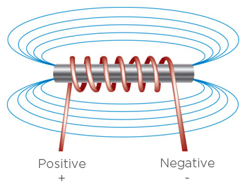
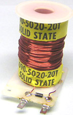
Coils (or solenoids) are just giant spools of wire around a non-conductive plastic tube. When electricity is applied to each end of the wire, a magnetic field is produced.
The strength of that field depends on the wire thickness, length and voltage used. Single-wound coils - ones with two connectors - do not have a polarity and can be hooked up in any direction. This magnetic field can be then used to impart movement on a metal plunger that slides inside the plastic tube. In pinball, that plunger is connected to things like flippers, slingshots, pop bumper rings, and so on, in order to impart that kinetic energy to the pinball in the game.
Coils are generally connected using a Ground Sink method, where one connector of the coil is attached to the positive lead of the high current power supply and the other connector goes to the controller board, where it attaches to a transistor, and when that transistor is activated by the game, the negative (ground) lead of the power supply is connected inside the transistor, allowing current to flow through the connected coil, which generates the magnetic field. It is done this way to lower the current load on the transistor.
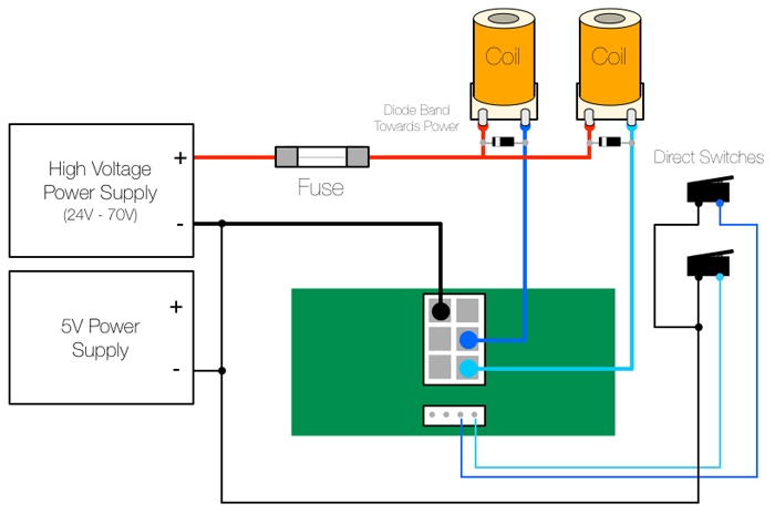
For an example of this wiring, here is the wiring diagram for the Open Pinball Project solenoid wing.
It shows a number of different devices but the key connections are between the high current power supply, the board, and the coils, showing how the negative lead of the power supply goes to the board, while the positive goes directly to the coil.
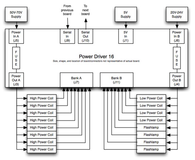
For P-ROC/P3-ROC, the connection method is slightly different, in that voltages and ground are connected from the board instead of from the power supplies separately, as per this diagram.
Diode
Depending on your controller, you may or may not need a Diode connecting the two leads on your coils. The reason for this diode is that when a coil's magnetic field collapses when power is stopped, it produces an in-rush of current in the opposite direction - a Flyback voltage. The diode is there to shunt that back into the coil to avoid damaging the transistors.
P-ROC/P3-ROC and FAST controllers do not need them as they have built-in flyback protection, while OPP and other original manufacturer boards do require external diodes. Make sure to confirm the need for diodes prior to wiring a game.
Lamps
Lamps could be incandescent, and thus work similarly to how coils work, with similar wiring. However all modern games have moved to LED lighting which comes in two types - direct wired or serial chain.
Direct Wired LEDs
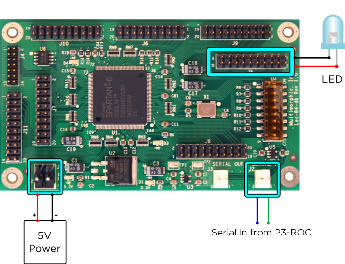
Direct wired LEDs are driven individually. The PD-LED can drive up to 84 single color LEDs or 28 RGB LEDs, for example.
The below diagram shows how to connect a single LED to the PD-LED.
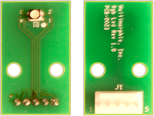
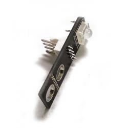
There are a number of options for under playfield mounting of LEDs, such as the Multimorphic RGB LED board or the Pinball Life RGB LED.
Serial Chain LEDs
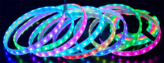
Serial Chain LEDs are LEDs that are daisy-chained together and use a serial protocol to accept commands to light up and are usually full colour RGB (red/green/blue). This means they can be programmed to light any colour.
They come in a variety of styles.
| Part Number | Number of Pins | Power |
|---|---|---|
| WS2801 | 4 wires (ground, power, clock, data) | 3.3V-5V |
| LPD8806 | 4 wires (ground, power, clock, data) | 3.3V-5.1V |
| WS2812B | 3 wires (ground, power, data) | 3.1V-5.2V |
Very simply, you send commands via the Serial Protocol to say "Lamp 5, turn Red", and the command is sent down the line until the fifth lamp sees it and turns red.
Thanks to modern pinball frameworks, all this low-level signalling is handled for you, so they can be labelled and addressed almost as simply as explained above.
Direct versus Serial
At first glance, serial LEDs would seem to have a big advantage over direct LEDs as the packing and wiring is much simpler, and overall are much cheaper as RGB LED strings are available for pennies per light on eBay and Aliexpress. However, they have two important drawbacks:
- Susceptible to interference: The underside of a pinball machine is a very noisy place in terms of EM emissions due to all the coils and mechs. As such, it can interfere with the serial communications, making lights not work, or light the wrong colour.
- Slower response time: Since the serial commands need to be sent from one light to the next in series versus in parallel for the direct LEDs, often the lights can be a bit slower to react to commands and cause issues with a complex lightshow.
For this reason, it's recommended to use direct LEDs under the playfield, while you can use limited strings of serial LEDs above the playfield.
The PD-LED can also drive both types of LEDs: Connector J8 is designated for serial LEDs specifically and can drive up to six LED chains.
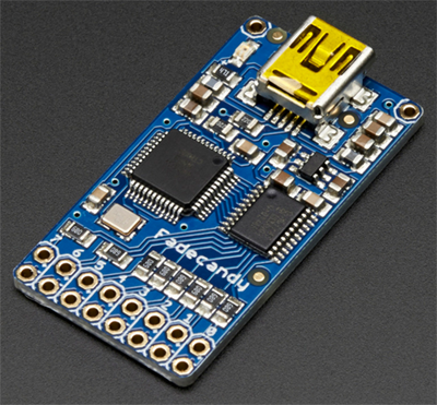
One option for controlling serial LEDs is the FadeCandy, which can control up to eight LED chains (with 64 LEDs each for a total of 512 LEDs) via the USB interface and is natively supported by MPF. It can update them at up to 400Hz and provides temporal dithering and smooth hardware fades.
Switches
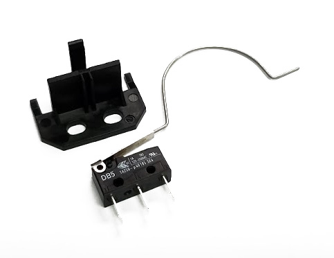
Switches come in a variety of types but the most common is the Microswitch. They come in a variety of sizes and newton force values (ie. easier or harder to activate). Pinball Life sells a generic rollover that covers most uses, although there are a number of different arm and mounting configurations possible.
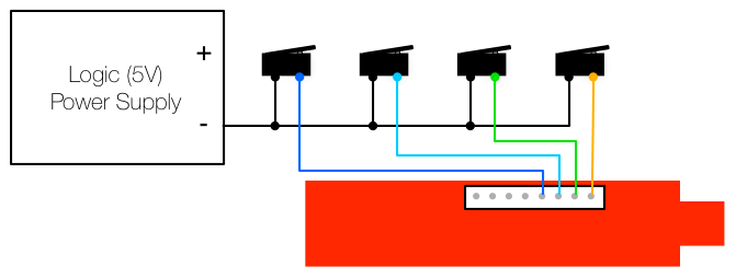
Wiring of switches is generally normally open with ground sink. The switch is wired to ground on one side and the controller board on the other, and when pressed, it connects ground to the controller, registering as closed.
Below is an example of the wiring for switches with Open Pinball Project.
