Difference between revisions of "OPP"
(→Solenoid Wing) |
(→Solenoid Wing) |
||
| Line 30: | Line 30: | ||
Note that the '''OPP''' boards support ''direct control'' switch programming, so that such devices can be configured in the firmware itself, and the 4-pin connector can cause some packaging issues, so it is recommended to leave the 4-pin connector out when building the boards unless you need it specifically. | Note that the '''OPP''' boards support ''direct control'' switch programming, so that such devices can be configured in the firmware itself, and the 4-pin connector can cause some packaging issues, so it is recommended to leave the 4-pin connector out when building the boards unless you need it specifically. | ||
| + | |||
| + | === Incandescent Wing === | ||
| + | |||
| + | The ''Incandescent'' wing uses [http://www.digikey.com/product-detail/en/fairchild-semiconductor/2N7000/2N7000FS-ND/244278 2N7000 MOSFETs] to control up to eight direct wired incandescent lamps via the same ''ground sink'' method as the coils. | ||
| + | |||
| + | [[Image:incandescent-wing.png]] | ||
| + | |||
| + | ''Direct wired'' means that each lamp is wired up and controlled individually via the 8-pin connector, rather than in the ''Matrix'' style that most commercial pinball machines used until recently. | ||
| + | |||
| + | The other 2-pin connector is for the ground connection. | ||
| + | |||
| + | === Interface Wing === | ||
| + | |||
| + | The ''Interface'' wing has no transistors or other electronic parts on it other than connectors. Its purpose is to distribute low voltage power (primarily 5V) and serial connections between each ''Processor'' board. | ||
| + | |||
| + | [[Image:interface-wing.png]] | ||
Revision as of 19:25, 17 August 2016
Contents
Open Pinball Project
The Open Pinball Project (OPP) was started in 2012 as a resource for pinball makers to have an inexpensive, fully open sourced project for controlling custom pinball machines. It is currently on a second generation design and has had a successful Kickstarter run of boards and components currently in the hands of makers all over the world.
Hardware
The OPP hardware is made up of three main components:
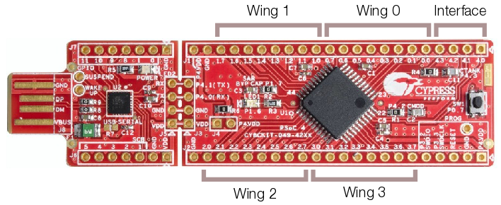
- The Processor board is a Cypress Semiconductor CY8CKIT-049-42XX PSoC prototyping board that can be purchased from Mouser or Digikey
- The Interface board allows communications between Processor boards via a custom serial communications protocol
- The Wing boards allow the control of solenoids, lamps, LEDs or input from switches
Processor Boards
The Processor board can control up to four Wing boards controlling solenoids, incandescent lamps, or allowing input for switches. The Wing boards themselves can be combined in any configuration, so a single Processor board can support up to 16 solenoids, 32 switch inputs or 32 lamps. Each Wing board uses eight pins while the Interface board uses four.
All other pins are unused, except on the first board in the chain where the USB plug from the host controller is connected and is connected to the Interface board to provide power and serial connections for the other Processors in the chain.
The Processor itself does not run game rules or other game logic - a Controller like Mission Pinball running on a separate PC is still required to handle scoring and other game logic and to fire coils and light lamps as needed. The Processor simply provides the physical connection to playfield devices.
Solenoid Wing
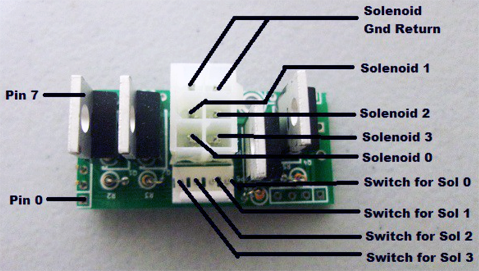
The Solenoid wing uses FQP13N06L MOSFETs to control up to four individual coils via a ground sink method, where the coils themselves are wired to the positive side of the high voltage power supply and the MOSFET provides a ground path when activated, firing the coil.
There are two connectors on the Solenoid wing - the larger 6-pin has four pins for the coil connections and two for ground. The 4-pin connector is for direct control switch inputs, for devices like slingshots or pop bumpers that require fast response to switch hits in order to fire coils.
Note that the OPP boards support direct control switch programming, so that such devices can be configured in the firmware itself, and the 4-pin connector can cause some packaging issues, so it is recommended to leave the 4-pin connector out when building the boards unless you need it specifically.
Incandescent Wing
The Incandescent wing uses 2N7000 MOSFETs to control up to eight direct wired incandescent lamps via the same ground sink method as the coils.
Direct wired means that each lamp is wired up and controlled individually via the 8-pin connector, rather than in the Matrix style that most commercial pinball machines used until recently.
The other 2-pin connector is for the ground connection.
Interface Wing
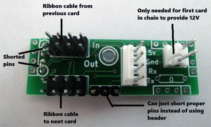
The Interface wing has no transistors or other electronic parts on it other than connectors. Its purpose is to distribute low voltage power (primarily 5V) and serial connections between each Processor board.


