Difference between revisions of "CobraPin"
Tfulenwider (talk | contribs) (→Switch Inputs) |
Tfulenwider (talk | contribs) (→Coil Ouputs) |
||
| Line 44: | Line 44: | ||
Each coil output has a diode to help protect the transistor. You may still use coils with axial diodes installed, but you '''MUST''' ensure that you connect them with the '''correct polarity'''. | Each coil output has a diode to help protect the transistor. You may still use coils with axial diodes installed, but you '''MUST''' ensure that you connect them with the '''correct polarity'''. | ||
| + | |||
| + | Every coil in a bank should be powered by the associated bank power pin on J13. For example, coils in Bank A should be powered by the HV_A pin of J13. | ||
'''J6''': Coil bank A outputs | '''J6''': Coil bank A outputs | ||
Revision as of 20:26, 11 February 2021
Contents
CobraPin Pinball Controller
This page is under construction
Overview
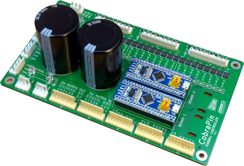
CobraPin is a pinball controller designed to offer a basic all-in-one assembled affordable solution. It is intended to be hosted by a computer running the Mission Pinball Framework (MPF) and is based on the Open Pinball Project (OPP) It will be released to the public in 2021 on Kickstarter.
Features:
- 24 coil drivers for solenoids, flashers, motors, etc. Outputs are broken out into 3 banks of 8 outputs.
- 38 direct switch inputs <OR> 22 direct inputs and an 8x8 switch matrix
- Neopixel support for 512 RGB or RGBW LEDs
- 24-50V power filter. Board also provides the common ground for the supplies.
- Fuses for solenoid banks and Neopixels
- Easy replacement of at-risk components
- Processor boards are socketed
- Transistors can be removed with simple soldering tools and replaced with through-hole components
- Fuse clips for common 5x20mm fuses
Future Hardware Plans
Expansion Board
An expansion board for CobraPin is planned, but not yet complete. It should support a lamp matrix, 8 additional coil outputs, and 8 additional direct inputs. The purpose of the expansion board is to make it easier for people to control existing machines with flashers and matrix controlled lamps.
Segment Displays
While regular segment displays will not be supported by CobraPin, custom alphanumeric boards are planned. These will likely be controlled by the neopixel output although they will be mono color. Each segment will act as a neopixel channel. For example, a WPC89 16x2 character display would take at least 182 effective neopixels out of the 512 available on the CobraPin.
Wiring
Power Input
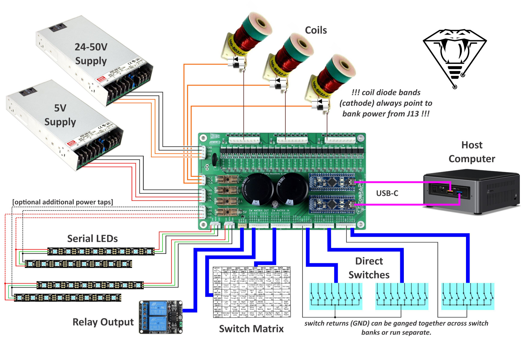
Power comes in to the board on two 4-pin 3.96mm pitch connectors. The default connectors are JST VH style. The pinout is labelled in silkscreen on the board.
J9: Coil power input (24-50V)
J10: Neopixel 5V input
Coil Power Output
The output power for the coils comes from a 3-pin 3.96mm JST VH style connector. These outputs are fused by F1, F2, and F3. Each pin provides an output for one of the coil banks. The pinout is labelled in silkscreen on the board.
J13: Coil power outputs
Coil Ouputs
The 24 coils are broken up into 3 banks of 8 outputs. The 3 9-pin 3.96mm connectors are JST VH style. There is a ninth pin on the connector that can be used as a key. That pin is marked by an asterisk in silkscreen. The coil outputs are labeled in silkscreen with the MPF compatible numbers.
Each coil output has a diode to help protect the transistor. You may still use coils with axial diodes installed, but you MUST ensure that you connect them with the correct polarity.
Every coil in a bank should be powered by the associated bank power pin on J13. For example, coils in Bank A should be powered by the HV_A pin of J13.
J6: Coil bank A outputs
J7: Coil bank B outputs
J8: Coil bank C outputs
Each bank has an LED next to it to indicate if that bank has power. Check these if you are concerned you have blown a fuse.
Each solenoid has an associated yellow LED to indicate it is being driven by the processor. It is highly recommended to test a new setup without high voltage power or without the coils plugged in. Using these LEDs, you can verify that each output is being driven correctly.
Switch Inputs
There are 5 9-pin 2.54mm pitch KF2510 style connectors for switches. The switch inputs are labeled in silkscreen with the MPF compatible numbers. Each connector also includes a logic ground pin. Use this for the direct input return. The two pins labeled “N/C” are not connected to anything.
J1, J2, J3: Direct input switches.
J4, J5: Remaining direct input switches <OR> switch matrix input/output. See MPF section below for switch matrix anomalies
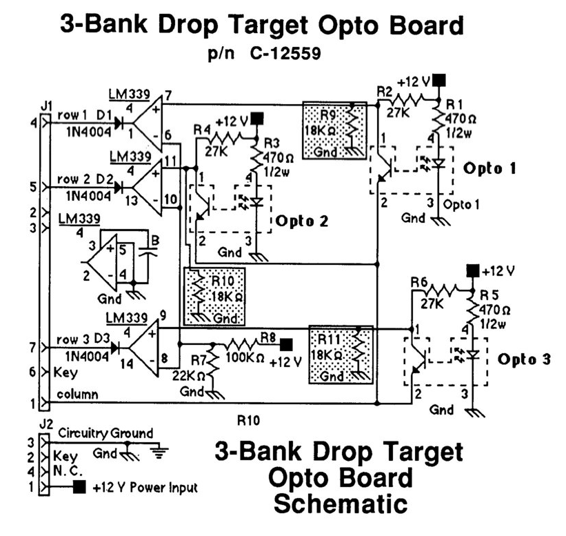
WARNING the switch inputs should be limited to 3.3V since the STM32 is a 3.3V device. If you are using an active switch like a drop target opto board, make sure none of the switch pins can go above 3.3V.
For example, the 5768-12368-00 drop target opto board from Police Force requires 10k resistors in the R9, R10, and R11 positions (see below) to keep the column voltage under 3.3V. If you do not do this, the opto board will try to the pull the column up to 12V. If you only use the 18k resistors suggested in the manual, the voltage will be limited to 4.8V...which is still too high.
Your other option in the case of 5768-12368-00 is to power the drop target board off of 3.3V instead of 12V so there are no higher voltages even present on the board. This would require changing R1, R3, R5 to 100ohms (standard 1/4W resistor would be fine) in order to drive the opto with a similar current given the lower drive voltage. The LM339 should operate fine at 3.3V.
Neopixel RGB LEDs
There are two neopixel chains that support 256 RGB pixels each for a total of 512. These outputs are on 2 3-pin 3.96mm JST VH connectors. RGBW pixels are also possible.
The J14 fused output can be used to provide additional power taps in a neopixel chain. This is a 4-pin 3.96mm JST VH style connector. Each pin is rated for 7A continuous. The fuse holder is rated for 10A. The red D25 LED can be used to confirm you have a good fuse (F4) and are providing power for neopixels.
J11, J12: Neopixel outputs
J14: Fused 5V output
USB
The two processor boards are connected to the host computer via two separate micro-USB cables.
MPF Configuration
It is HIGHLY RECOMMENDED that you start your MPF game-making journey with the MPF Tutorial
For detailed MPF documentation, head over to MPF Docs
CobraPin specific info can be found here: CobraPin on MPF Docs
Switch Matrix
The switch matrix can be a little confusing. OPP drives its matrix output with HIGH pulses as opposed to pulsing LOW like Williams and others did. The switch matrix diodes should point from the CobraPin SW MATRIX OUT connector to the SW MATRIX IN connector. So the band on the diodes should be closer to the SW MATRIX IN connector.
This means you may have to swap your rows and columns connectors if you have a matrix from an old machine. If you do this, you will have to transpose your matrix switch numbering since the rows are columns and the columns are the rows now.
Additionally, switches inputs from a matrix in MPF appear to be inverted. So when a switch is open or OFF, it appears in MPF that it is closed or ON. To fix this, you have to invert it again. So you add "type: NC" to the switch definition of a normally-open matrix switch. The NC stands for Normally-Closed. I know it is backwards. Maybe we can fix it, but that is how it currently works.
Autofire Devices
Autofire devices use a configurable link between a switch and a coil output to control the coil with the absolute minimal latency by allowing the STM32 to directly control the coil rather than the control coming from the host computer. These should be used for timing critical coils like flipper, pop bumpers, and slings.
Note: an autofire coil must be controlled by a switch on the same STM32 board. So a 1-0-xx switch needs to control a 1-0-yy coil and a 0-0-xx switch needs to control a 0-0-yy coil.
STM32 Flashing and OPP Configuration
The firmware on the STM32 board exists in two parts: the base application and the OPP configuration. As delivered, the boards should be flashed and configured appropriately. But if you need to updated something or replace a processor board, this section is for you. The base application must be flashed with a separate programming device while the OPP configuration can be changed over USB via Python scripts.
Flashing
You can download a snapshot of the OPP source here: OPP Source
The STM32 firmware images can be found in the folder Stm32Workbench / Gen3Images /
Instructions for flashing the base application on to the STM32 board can be found here on the OPP site: Loading STM32 Firmware
Configuration
Pre-made config files can be found here: CobraPin STM32 Config Files
You can use these or modify them for your own needs. For example, OPP has the capability to operate in "whitewood mode." That means that switches can be assigned to coil outputs to control a machine in a basic way (flippers flipping, pops and slings firing, but no rules) before you have MPF up and running. This is setup in the config and is unique to your own machine.
Loading the Config
Standard Config
The Standard CobraPin Config includes 24 coil outputs, switch matrix, 22 direct inputs, and 512 neopixels that glow dimly blue at power-on. The purpose of glowing dimly is to verify at a glance that all pixels are operating properly even before MPF takes control of the lights. If you don't want this, you can replace the config with a "No Glow" variant.
Standard No Glow
The Standard No Glow CobraPin Config is the same as Standard but the neopixels will not light until MPF takes control of them.
Direct Config
The Direct CobraPin Config includes 24 coil outputs, 38 direct inputs, and 512 neopixels that glow dimly blue at power-on. The purpose of glowing dimly is to verify at a glance that all pixels are operating properly even before MPF takes control of the lights. If you don't want this, you can replace the config with a "No Glow" variant. This trades the switch matrix for 16 extra direct inputs.
Direct No Glow
The Direct No Glow CobraPin Config is the same as Direct but the neopixels will not light until MPF takes control of them.


