Difference between revisions of "CobraPin"
Tfulenwider (talk | contribs) (→Fuse) |
Tfulenwider (talk | contribs) (→Scenarios) |
||
| Line 277: | Line 277: | ||
Symptom: Neopixel chain does not glow blue on startup | Symptom: Neopixel chain does not glow blue on startup | ||
Things to check: | Things to check: | ||
| − | 1 | + | 1. Do you have 5V applied to the board at J10? |
| − | + | 2. Is the fuse blown? Check the red 5V LED on the CobraPin board | |
| − | + | 3. Does another set of neopixels work when plugged in? | |
| − | + | 4. Do you have a NoGlow config loaded? | |
</pre> | </pre> | ||
Revision as of 05:28, 2 July 2021
Contents
CobraPin Pinball Controller
Overview
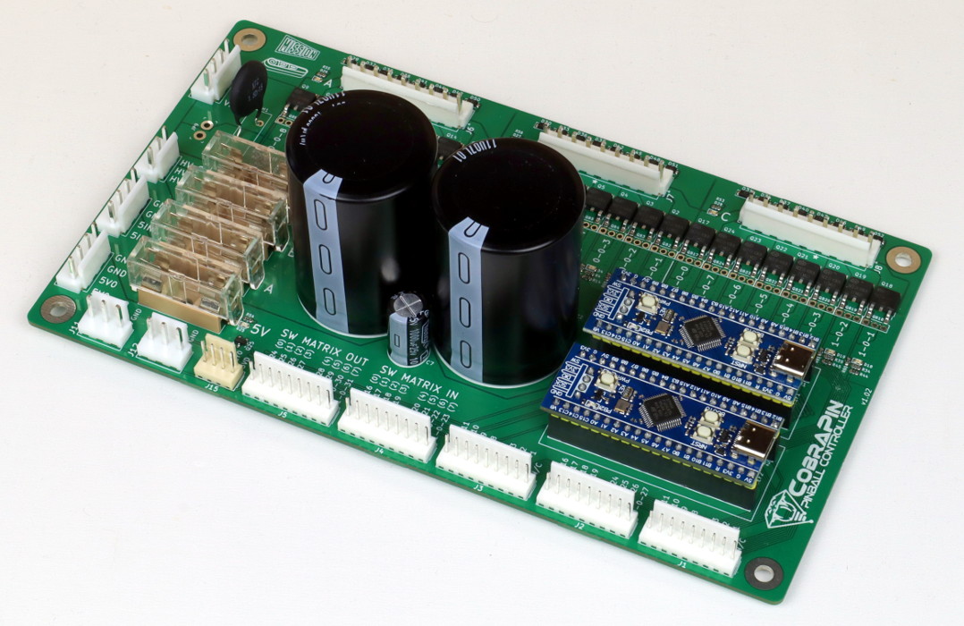
CobraPin is a pinball controller designed to offer a basic all-in-one assembled affordable solution. It is intended to be hosted by a computer running the Mission Pinball Framework (MPF) and is based on the Open Pinball Project (OPP) It will be released to the public in 2021 on Kickstarter.
Features:
- 24 coil drivers for solenoids, flashers, motors, etc. Outputs are broken out into 3 banks of 8 outputs.
- 38 direct switch inputs <OR> 22 direct inputs and an 8x8 switch matrix
- Neopixel support for 512 RGB or RGBW LEDs
- 24-50V power filter. Board also provides the common ground for the supplies.
- Fuses for solenoid banks and Neopixels
- Relay Control Output for common dual relay boards
- Easy replacement of at-risk components
- Processor boards are socketed
- Transistors can be removed with simple soldering tools and replaced with through-hole components
- Fuse clips for common 5x20mm fuses
Future Hardware Plans
Xpansion Board
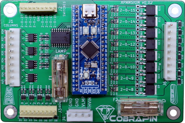
The Xpansion is a prototype expansion board for CobraPin. It supports a lamp matrix, 8 additional coil outputs, and 8 additional direct inputs. The purpose of the expansion board is to make it easier for people to control existing machines with flashers and matrix controlled lamps.
Segment Displays
While regular segment displays will not be supported by CobraPin, custom alphanumeric boards are under development.
A 7-digit prototype was created that is controlled by the neopixel output and the display is mono color. Multiple color options are available. Each segment acts as a neopixel channel, so it takes the equivalent of 42 pixels to create a 7-digit display. Multiple displays can be daisy-chained together, so you can have up to 6 displays on a single CobraPin output channel (6 x 42 = 252 < 256). You can also arrange 4 displays together to create a 14x2 display that fits in the same area as something like a WPC89 display.
Shown here are two displays next to each other, a red and blue.
Wiring
Power Input
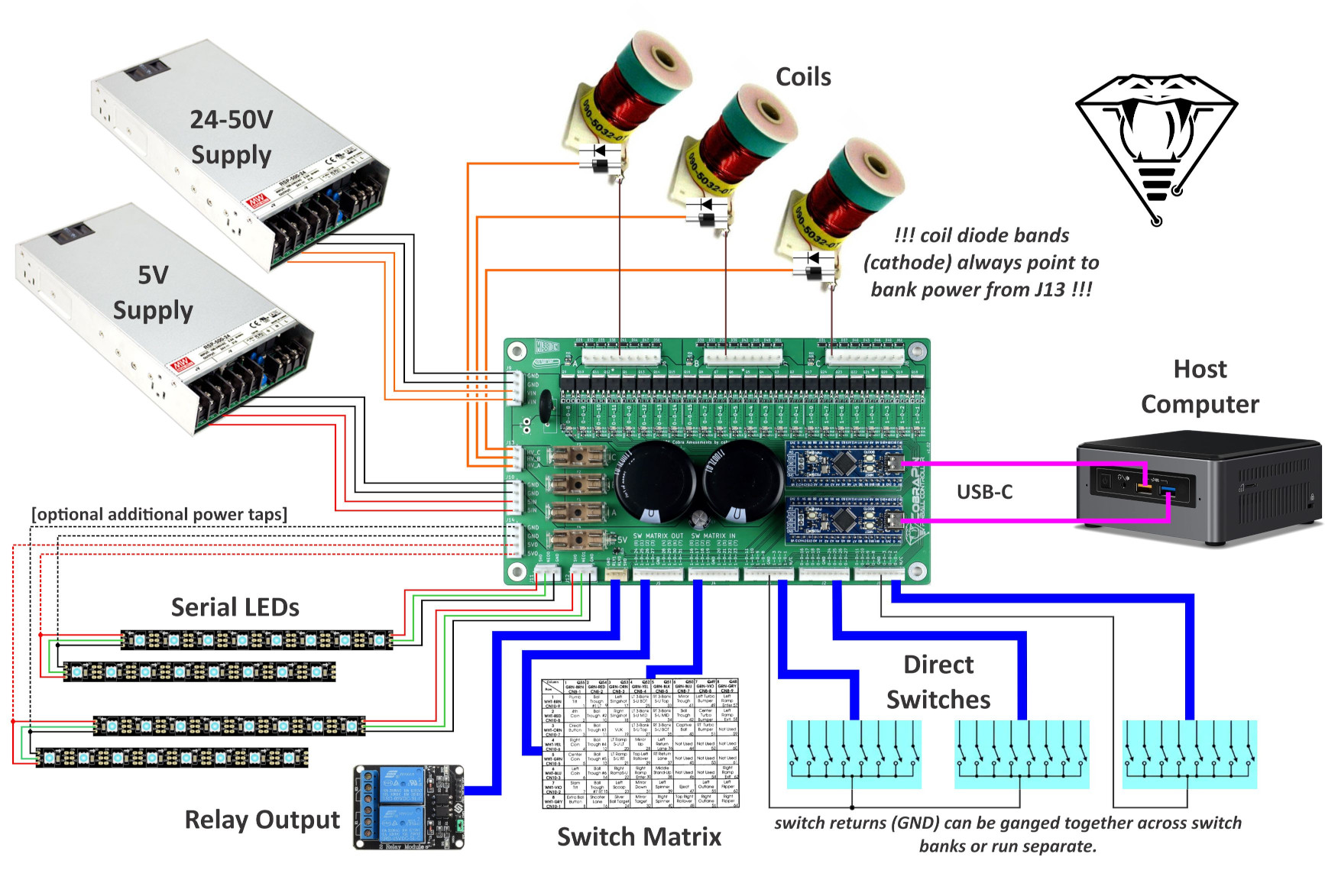
Power comes in to the board on two 4-pin 3.96mm pitch connectors. The default connectors are JST VH style. The pinout is labeled in silkscreen on the board.
J9: Coil power input (24-50V).
J10: Neopixel 5V input
Coil Power Supply Requirement
Since CobraPin has large capacitors, it takes high current for a short time to charge them up at initial power-on. Most switch mode power supplies (digital rather than the old transformers) have overload protection that kick in during this initial power-on state. Some protection modes are incompatible with CobraPin. The incompatible protection modes will just shut off while trying to charge the capacitors. Nothing bad happens, but you just don't have power.
DO NOT use a power supply that shuts down its output in an overload state. Meanwell SE series is an examples of this. This is not an exhaustive list.
DO use a power supply with constant-current limiting or something that says "recovers automatically" for overload protection. Meanwell RSP, HRP, and MSP series are examples of this. This is not an exhaustive list. Most generic power supplies sold for LED strip lighting applications have constant current limiting.
Power Jumper
JP9: The input goes through an NTC thermistor to limit the load on the power supply when it first turns on and charges the large power capacitors. When cold, the thermistor is about 1.5ohms, as it heats up, the resistance drops considerably (1/10th or 1/20th of the cold resistance). If you find that the first minute of play is too weak, you can bypass the thermistor by soldering a wire at JP9. This will further load your power supply at startup, so proceed with caution.
Coil Power Output
The output power for the coils comes from a 3-pin 3.96mm JST VH style connector. These outputs are fused by F1, F2, and F3. Each pin provides an output for one of the coil banks. The pinout is labeled in silkscreen on the board.
J13: Coil power outputs. Each pin should be used to power the coils in its corresponding bank.
Coil Ouputs
The 24 coils are broken up into 3 banks of 8 outputs. The 3 9-pin 3.96mm connectors are JST VH style. There is a ninth pin on the connector that can be used as a key. That pin is marked by an asterisk in silkscreen. The coil outputs are labeled in silkscreen with the MPF compatible numbers.
Each coil output has a diode to help protect the transistor. You may still use coils with axial diodes installed, but you MUST ensure that you connect them with the correct polarity.
Every coil in a bank should be powered by the associated bank power pin on J13. For example, coils in Bank A should be powered by the HV_A pin of J13.
J6: Coil bank A outputs
J7: Coil bank B outputs
J8: Coil bank C outputs
Each bank has an LED next to it to indicate if that bank has power. Check these if you are concerned you have blown a fuse.
Each solenoid has an associated yellow LED to indicate it is being driven by the processor. It is highly recommended to test a new setup without high voltage power or without the coils plugged in. Using these LEDs, you can verify that each output is being driven correctly.
Switch Inputs
There are 5 9-pin 2.54mm pitch KF2510 style connectors for switches. The switch inputs are labeled in silkscreen with the MPF compatible numbers. Each connector also includes a logic ground pin. Use this for the direct input return. The two pins labeled “N/C” are not connected to anything.
J1, J2, J3: Direct input switches.
J4, J5: Remaining direct input switches <OR> switch matrix input/output. The matrix row and column numbers are labeled in silkscreen in parentheses. See MPF section below for switch matrix anomalies.
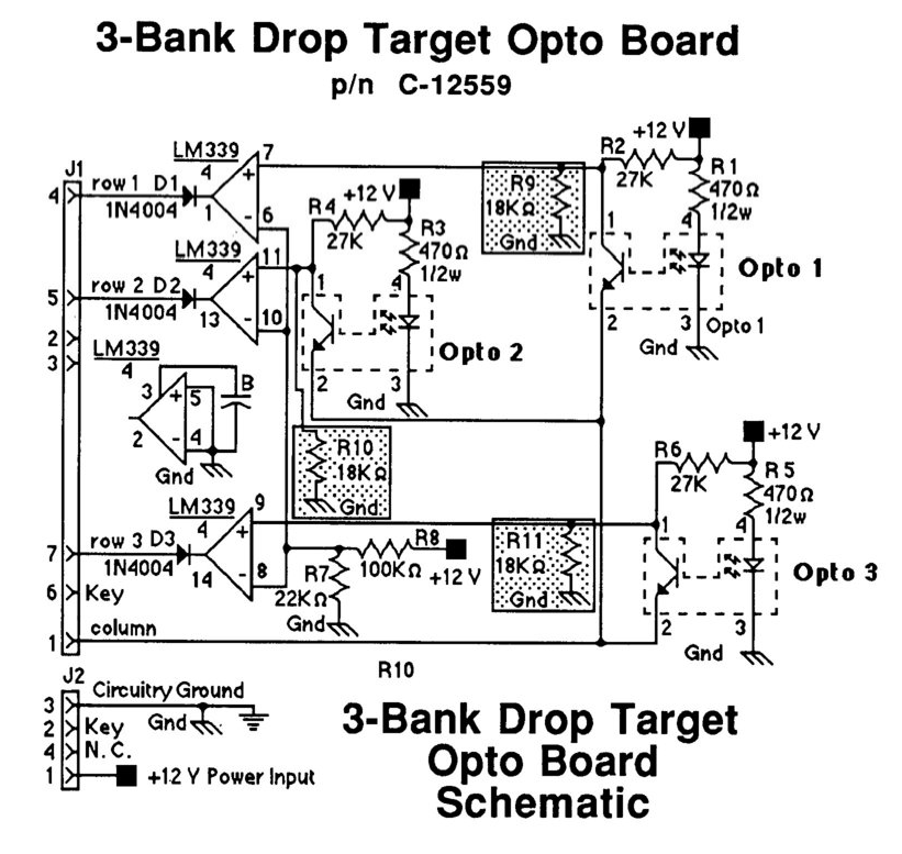
WARNING: the switch inputs should be limited to 3.3V since the STM32 is a 3.3V device. If you are using an active switch like a drop target opto board, make sure none of the switch pins can go above 3.3V.
For example, the 5768-12368-00 drop target opto board from Police Force requires 10k resistors in the R9, R10, and R11 positions (see below) to keep the column voltage under 3.3V. If you do not do this, the opto board will try to the pull the column up to 12V. If you only use the 18k resistors suggested in the manual, the voltage will be limited to 4.8V...which is still too high.
Your other option in the case of 5768-12368-00 is to power the drop target board off of 3.3V instead of 12V so there are no higher voltages even present on the board. This would require changing R1, R3, R5 to 100ohms (standard 1/4W resistor would be fine) in order to drive the opto with a similar current given the lower drive voltage. The LM339 should operate fine at 3.3V.
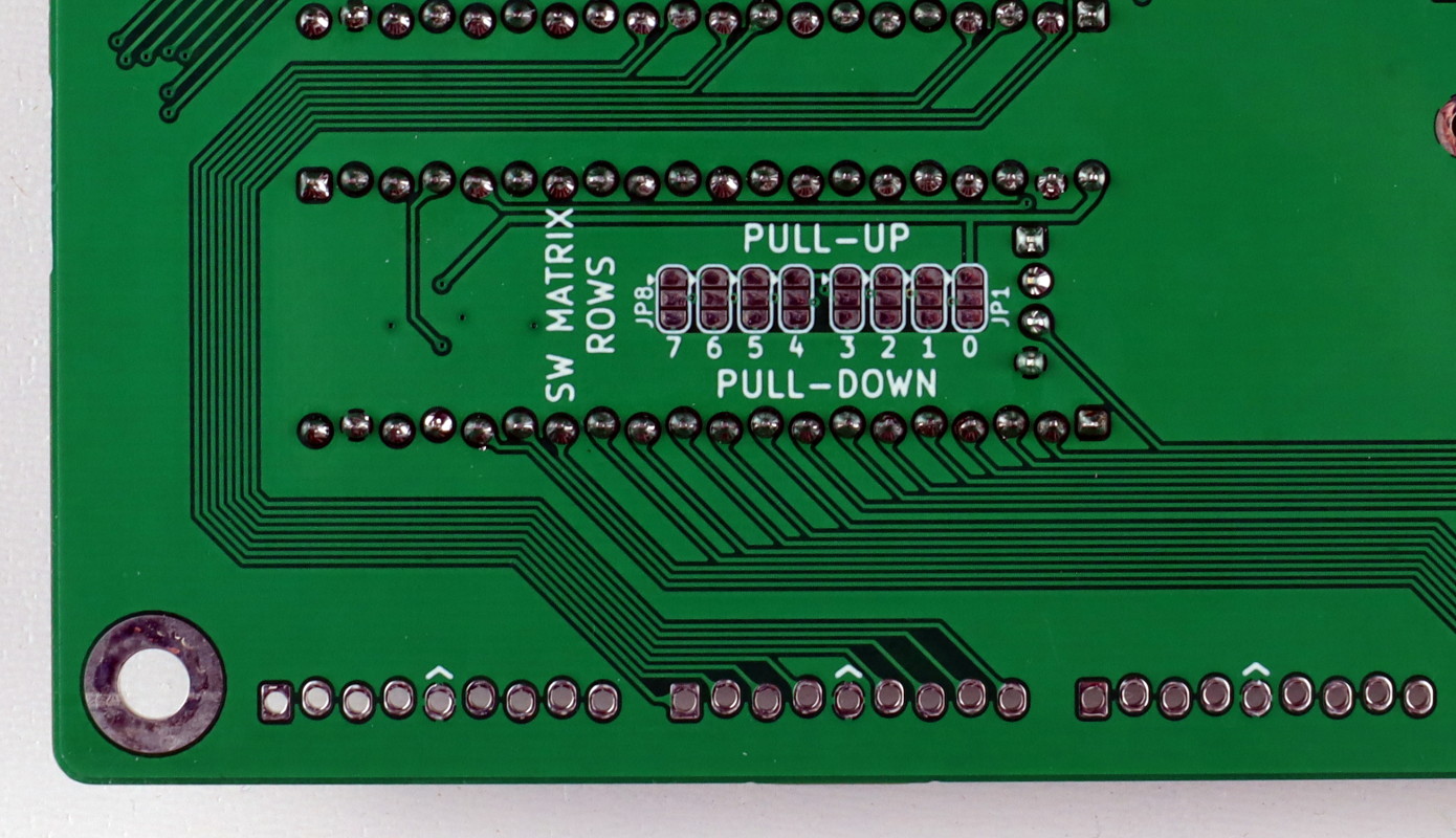
Matrix Row Pull Resistor Jumpers
When using optos in a switch matrix, sometimes the internal pull resistors on the switch matrix inputs (rows) are not strong enough to register opto inputs properly. If this becomes a problem, you can use the onboard pull resistors to augment the internal resistors in the STM32. To do so, make a solder bridge on the 8 row jumpers (JP1-8) on the underside of the board. If you have a standard active-low matrix, then the solder jumper needs to be on the PULL_UP side. If you are instead using and active-high matrix, the jumper should be on the PULL_DOWN side.
WARNING: DO NOT connect all three pads of a jumper together. This would short 3.3V and GND together and will likely destroy the STM32 processor board.
Neopixel RGB LEDs
There are two neopixel chains that support 256 RGB pixels each for a total of 512. These outputs are on 2 3-pin 3.96mm JST VH connectors. RGBW pixels are also possible.
The J14 fused output can be used to provide additional power taps in a neopixel chain. This is a 4-pin 3.96mm JST VH style connector. Each pin is rated for 7A continuous. The fuse holder is rated for 10A. The red D25 LED can be used to confirm you have a good fuse (F4) and are providing power for neopixels.
J11: NEO 0 Neopixel output (all these lights have MPF numbers with the format 0-0-##).
J12: NEO 1 Neopixel output (all these lights have MPF numbers with the format 1-0-##).
J14: Fused 5V output
USB
The two processor boards are connected to the host computer via two separate USB-C cables (the beta version used micro-USB cables).
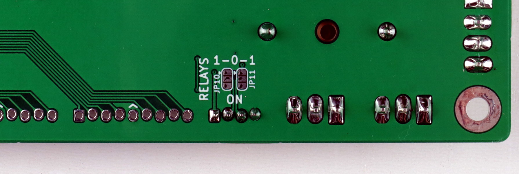
Relay Control Output
CobraPin can drive a dual relay board commonly sold for Arduino applications. These relay boards are powered by 5V and are driven by two control signals. The 5V power for the relay control comes from the Board 1 USB power.
By default, nothing is connected to the two control outputs. On the underside of the CobraPin are two 3-way solder jumpers. Each jumper controls how one of the control outputs is driven. Connecting the middle and lower pad enables that relay control output any time there is USB power to the Board 1 processor board. Connecting the middle and upper pads gives control of the relay programmatically to MPF by using the 1-0-1 coil output.
Note: When using the 1-0-1 coil output for relay control, do not use the 1-0-1 output on J8. These are controlled by the same processor pin.
J15: 5V power and control for a dual relay board
MPF Configuration
It is HIGHLY RECOMMENDED that you start your MPF game-making journey with the MPF Tutorial
You should install version 0.55 or higher of MPF. As of 20210601, this means you need to install the dev version of MPF.
For detailed MPF documentation, head over to MPF Docs
CobraPin specific info can be found here: CobraPin on MPF Docs
An Example Config is available to help you start your game's config.
Switch Matrix
OPP now supports both active low and active high switch matrices. Active low and high refer to the direction that the columns are strobed in a switch matrix. The style that you want is selected by loading the respective OPP configuration into the STM32 board. See OPP Configuration below.
On CobraPin, the SW MATRIX OUT connector has the column outputs 0-7 and the SW MATRIX IN connector has the row inputs 0-7.
The default Standard configuration of CobraPin uses an active low matrix.
Active Low Matrix
An active low matrix pulls a column down when it is selected so that any active switch pulls the associated row down. In an active low matrix, the diodes always point toward the columns. Williams is an example of a manufacturer that always used an active low matrix.
Active High Matrix
In an active high matrix, the logic is just reversed. Columns pulse high so active switches are pulled high. The diodes point toward the rows. Gottlieb System 3 is an example of a system that used an active high matrix.
In many cases, you can use an active low matrix to drive a machine that was intended to have an active high matrix by just swapping the row and column connectors. Then the diodes will point to the columns as required for an active low matrix. If you do this, you will have to transpose your matrix switch numbering from what you might find in your game's manual since the rows are columns and the columns are the rows now. This method will work for simple mechanical but your mileage may vary on active switches like some optos and drop target banks.
Switches inputs from an active high matrix in MPF appear to be inverted. So when a switch is open or OFF, it appears in MPF that it is closed or ON. To fix this, you have to invert it again. So you add "type: NC" to the switch definition of a normally-open matrix switch. The NC stands for Normally-Closed. I know it is backwards, but that is how it works. This is not required for the Standard active low matrix
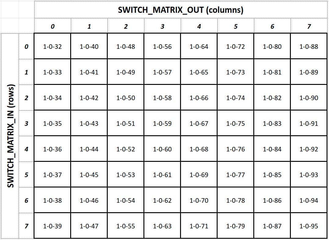
Matrix Numbering
The matrix is hosted by Board 1 on the CobraPin, so the valid numbers for switches are 1-0-32 through 1-0-95. See table below.
Autofire Devices
Autofire devices use a configurable link between a switch and a coil output to control the coil with the absolute minimal latency by allowing the STM32 to directly control the coil rather than the control coming from the host computer. These should be used for timing critical coils like flippers, pop bumpers, and slings.
Note: an autofire coil must be controlled by a switch on the same STM32 board. So a 1-0-xx switch needs to control a 1-0-yy coil and a 0-0-xx switch needs to control a 0-0-yy coil.
STM32 Flashing and OPP Configuration
The firmware on the STM32 board exists in two parts: the base application and the OPP configuration.
As delivered, the boards should be flashed and configured appropriately. But if you need to updated something or replace a processor board, this section is for you.
The base application must be flashed with a separate programming device while the OPP configuration can be changed over USB via Python scripts.
Flashing
You can download a snapshot of the OPP source here: OPP Source
The STM32 firmware images can be found in the folder Stm32Workbench / Gen3Images /
Instructions for flashing the base application on to the STM32 board can be found here on the OPP site: Loading STM32 Firmware
Configuration
Pre-made config files can be found here: CobraPin STM32 Config Files
You can use these or modify them for your own needs. For example, OPP has the capability to operate in "whitewood mode." That means that switches can be assigned to coil outputs to control a machine in a basic way (flippers flipping, pops and slings firing, but no rules) before you have MPF up and running. This is setup in the config and is unique to your own machine.
There are two processor boards on the CobraPin with the board numbers labeled on silkscreen under the boards. Board 0 is the upper board and Board 1 is the lower board. Each board requires a different config and should not be swapped without re-configuring OPP.
Putting a Board 1 config in a Board 0 slot could result in blown FETs, coils, or fuses. A Board 0 config should also not go in the Board 1 slot. Proceed with caution!
Board 0
Regular: Neopixels on J11 that glow dimly blue at power-on. The purpose of glowing dimly is to verify at a glance that all pixels are operating properly even before MPF takes control of the lights.
NoGlow: Neopixels on J11 will stay off at power up.
Board 1
There are 3 variants for Board 1. By default, all of them have neopixels on J12 that glow dimly blue at power-on. The purpose of glowing dimly is to verify at a glance that all pixels are operating properly even before MPF takes control of the lights. Each variant also has a NoGlow option.
Standard: Includes the standard active-low matrix for 64 matrix switches and 22 direct inputs.
Direct: No matrix for a total of 38 direct inputs on the CobraPin.
HighMatrix: Includes an active-high matrix for 64 matrix switches and 22 direct inputs.
Loading the Config
The OPP Config Process consists of establishing comms, erasing the existing config, loading/saving the new config, and verifying the new config. Note that Gen2Test is a Python 2 script while MPF uses Python 3. You must have both Python versions to configure OPP and run MPF.
Since CobraPin relies on processor board serial numbers to address the boards, use Gen2Test to load the serial number. The serial should be the board number (0,1,2, etc.).
As an example, here is the command sequence to load the regular config into Board 0. You may have a different port name.
python Gen2Test.py -port=/dev/ttyACM0
python Gen2Test.py -port=/dev/ttyACM0 -eraseCfg
python Gen2Test.py -port=/dev/ttyACM0 -saveCfg -loadCfg=CobraPin_Board0.py
python Gen2Test.py -port=/dev/ttyACM0
python Gen2Test.py -port=/dev/ttyACM0 -ser=0
Troubleshooting
You should always try a new or significantly changed setup WITHOUT coil power. Use the yellow coil LEDs on CobraPin to check if the coil outputs are behaving as expected.
LEDs on the STM32
Each STM32 board has a power LED and an LED connected to a processor pin. For the USB-C version of the STM32 board that is shipped with CobraPin, the blue LED connected to pin PB21 has a useful troubleshooting purpose. It is a heartbeat and activity indicator. The LED is toggled every second and whenever there is a USB packet received.
Toggling every second: The OPP firmware is running and it is not receiving any USB packets.
On dimly or changing like there is a lot of activity: The OPP firmware is running and is receiving USB packets. The host is communicating with it. This is the state when MPF is running a game.
Note: If you are using a micro-USB version of the STM32 board, you should ignore the LED connected to PC13. This pin is shared with an I/O pin used for another purpose and should not be used for troubleshooting.
Scenarios
Symptom: Coil not firing
Things to check:
   1. Is there a blown fuse? There are blue LEDs for banks A, B, and C.
      These will be lit if coil power is applied to the board and the
      fuses are good.
   2. Does the yellow LED associated with that channel light
      appropriately? This can be tested without coil power.
   3. Do you have continuity to your coil?
Symptom: Coil stuck on
Things to check:
   1. Is the yellow LED associated with that channel also stuck on?
      If so, is a Board 1 config accidentally loaded in a Board 0 slot?
   2. What is the resistance from the coil output pin to GND?
      Check this with power off, coils disconnected, red probe on coil
      output, black on GND. If the resistance is low, The FET is blown.
Symptom: All/many switches report as active or inverted in MPF
Things to check:
   1. Do you have the column/row connectors swapped?
   2. Are your matrix diodes pointed the correct direction given the
      style matrix you have?
   3. For an active-high matrix MPF requires a "type: NC" in the switch
      definition for a normally-open switch.
Symptom: Neopixel chain does not glow blue on startup
Things to check:
   1. Do you have 5V applied to the board at J10?
   2. Is the fuse blown? Check the red 5V LED on the CobraPin board
   3. Does another set of neopixels work when plugged in?
   4. Do you have a NoGlow config loaded?
Replacing Components
Static can break electronics. Avoid touching pins or components, when possible.
If you must touch them, use a conductive wrist strap to an earth ground, discharge yourself by touching grounded metal, or at least stop shuffling your feet on the carpet.
STM32 Processor Board
To remove a processor board, pull it out. Simple, but not always easy. Work it out slowly, always keeping it level with the CobraPin board. Failure to do so could result in bent pins or damaged female headers.
To install a board, ensure the USB connector faces toward the outside of the CobraPin (i.e. not facing straight into the power capacitors). Set the board in place and double-check that all the pins line up. Then carefully and slowly push the board straight down, keeping it level with the CobraPin board.
Transistor
Fuse
You should use slow blow 5x20mm fuses. The maximum allowable fuse is 10A.
1. Remove the clear plastic fuse cover
2. Gently pull out spent fuse
3. Push in new fuse trying to keep it level with the board and centered in the fuse holder
4. Replace fuse cover
5. Test your setup without powering the fuse first to make sure there are no software or configuration problems

