Difference between revisions of "P3-ROC"
(→Serial Wiring) |
(→DIP Switches) |
||
| Line 158: | Line 158: | ||
Each board includes an 8-position DIP switch, which is used to set the ID of the board in question, to terminate a chain of boards (DIP 8), and set some additional settings. | Each board includes an 8-position DIP switch, which is used to set the ID of the board in question, to terminate a chain of boards (DIP 8), and set some additional settings. | ||
| − | Each board needs a unique ID ''per serial chain'' - ie. you can have two ''Board 0''s as long as they are on different chains. '''DIP 1-6''' sets the ID in '''binary''' notation, starting at zero (All Off). So if you want to set the board ID to 5, you would set DIP 1 and | + | Each board needs a unique ID ''per serial chain'' - ie. you can have two ''Board 0''s as long as they are on different chains. '''DIP 1-6''' sets the ID in '''binary''' notation, starting at zero (All Off). So if you want to set the board ID to 5, you would set DIP 1 and 3 to ''On''. Or if you want to set the board ID to 0, leave all six ''Off''. If the board is the last board in the chain, set DIP 8 to ''On'' as well to terminate the serial chain. Boards connected earlier in the chain should have DIP 8 ''Off''. |
[[Image:DIP.png|400px|DIP Switch]] | [[Image:DIP.png|400px|DIP Switch]] | ||
Latest revision as of 21:10, 10 December 2018
The P3-ROC is the next evolution of the Multimorphic line of pinball controllers. Designed for use in their P3 modular system, it is well suited to custom game construction thanks to that very same modularity.
Hardware
The P3-ROC hardware consists of five main boards:
- P3-ROC is the main controller device which plugs into a PC via USB and allows the PC to communicate with the various input/output boards.
- PD-16 allows control of up to 16 solenoids or other high voltage devices.
- SW-16 supports up to 16 switch inputs.
- PD-LED allows control of up to 84 single LEDs or up to 2048 serial LEDs.
- Power Entry provides a simple and safe way to connect power between multiple power supplies and game devices.
Additionally, they provide a number of support devices such as long range optos, RGB LED boards and audio amps.
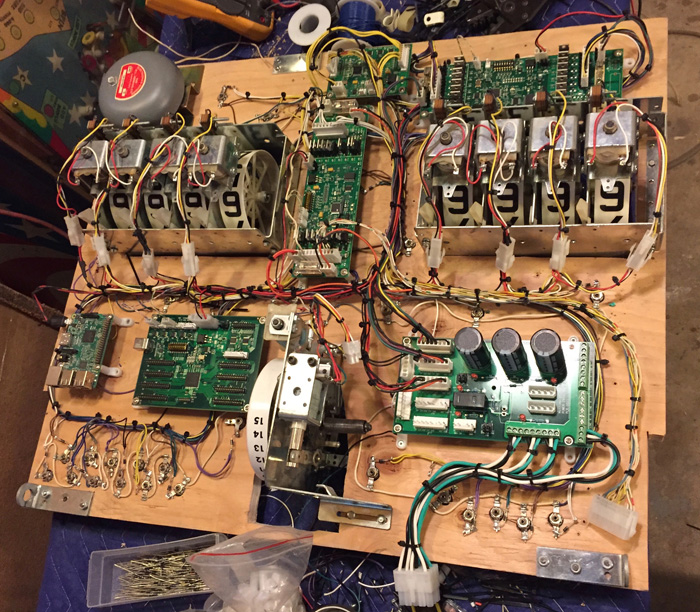
From top left moving clockwise: SW-16, 8x8 (deprecated matrix controller for lamps), PD-16, Power Entry, P3-ROC and RPi3 as controller PC
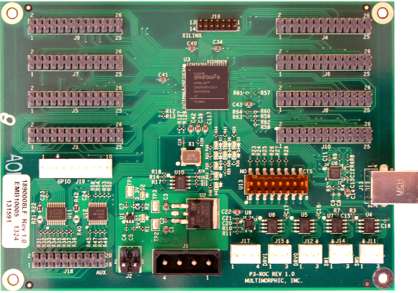
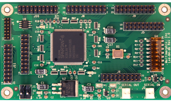
P3-ROC Controller Board
At the heart of the system is the P3-ROC Controller Board. All other boards communicate through it and it handles all the signalling needed, relieving the PC to handle game rules instead of switch matrix scanning, pulse-width modulation of coils, and other low-level device support.
Although it appears complicated due to the number of connectors on the board, the majority of the .100" headers are to support the P3 long-range optos and are not relevant to most custom game makers.
The theory of operation, dip switches and what the LEDs mean is explained in the documentation but the key connections are:
- J1: Power input (5V) using a standard PC power supply connector
- J2: Power input (5V) using standard pinball-style .156" Molex connector
- J11: Serial connector 0 (.100" Molex) for SW-16 switch boards
- J12: Serial connector 0 (.100" Molex) for PD-16 driver boards
- J13: USB connector to computer
- J14: Serial connector 1 (.100" Molex) for SW-16 switch boards
- J15: Serial connector 1 (.100" Molex) for PD-16 driver boards
- J17: I2C Serial connector (.100" Molex)
Serial Interface
The P3-ROC uses the RS-485 serial protocol to communicate to the attached boards. Designed for high EM environments, it has excellent error correction and robust signalling and is well suited for the noisy world under a pinball playfield.
Note that the Switch and Driver serial connectors have different pinouts, to help avoid mixing up connectors when assembling wiring.
There are a total of four serial connectors - two for switches (SW-16) and two for drivers (PD-16 and PD-LED). This allows for chains to easily extend to the backbox and playfield, or playfield and cabinet.
PD-16 Driver Board
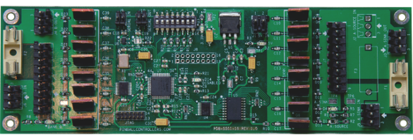
For controlling solenoids and other high current devices there is the PD-16 Driver board.
It uses 16 MOSFETs in a ground-sink configuration - high power devices are connected directly to the positive voltage, then connected to the PD-16 which activates the device by connecting it to ground. It is divided into two banks of 8, with in-rush diodes on all inputs to protect the board, so diodes are not required on solenoids.
From the documentation, the connections (all .156" Molex unless specified) are:
- J1: 5V input
- J3: Bank A High Power Out
- J4: Bank B High Power Out
- J5: Bank A High Power In
- J6: Bank B High Power In
- J7: Bank A Input (ground)
- J9: Serial In (.100" Molex)
- J10: Serial Out (.100" Molex)
- J11: Bank B Input (ground)
Power Connections
High power (24V - 70V) is connected directly to the PD-16, which is fused, then output from the board to the high power devices, or to additional PD-16s. In addition, 5V is required to run the onboard logic and serial communications.
SW-16 Switch Board
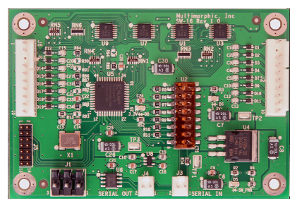
For reading individual switches, the SW-16 switch board is used.
The SW-16 uses 12V for switches and works opposite of the driver boards - ground is connected to the switches and when closed, completes the circuit on the board. It is divided into two banks of 8. The 12V switch power is stepped down to 5V to handle the on-board logic and serial.
Per the documentation, the connectors are:
- J1: 12V Power (.156" Molex)
- J2: Bank A Switch Inputs (.100" Molex)
- J3: Serial In (.100" Molex)
- J4: Serial Out (.100" Molex)
- J6: Bank B Switch Inputs (.100" Molex)
PD-LED Light Board
Modern pinball machines use LEDs (light emitting diodes) for lighting, and the PD-LED is designed to drive them.
The PD-LED can drive 84 individual LEDs using the seven 20-pin connectors on the board. Depending on the LED, power is supplied to the LEDs (resistors may be required depending on the forward voltage of the LED in question) and the cathode leg of the LED is connected to the PD-LED which grounds it to light. Some LEDs may be common anode so the wiring will be reversed.
Per the documentation, the connectors are as follows:
- J1: 5V Logic (.156" Molex)
- J2: Serial In (.100" Molex)
- J3: Serial Out (.100" Molex)
- J5: LED 0-11
- J6: LED 24-35
- J7: LED 48-59
- J8: LED 72-83 and Serial LED Control
- J9: LED 12-23
- J10: LED 36-47
- J11: LED 60-71
Serial LED Control
The PD-LED can also serially control LED strings via J8. The board will need to be configured for serial use, and the pins used for serial communications with the LED strings cannot be used for single LEDs, thus reducing the total LED capacity.
WS281x
Three strings of single wire WS281x-style serial LEDs can be controlled from pins 17-19. These type of serial LEDs do not have a clock signal so light shows may get out of sync with other events, but they are extremely inexpensive.
- J8 Pin 17: Serial Data 2
- J8 Pin 18: Serial Data 1
- J8 Pin 19: Serial Data 0
LPD880x
Three strings of LPD880x-style serial LEDs can be controlled from pins 7-9 and 12-14. These style include a clock signal for proper syncing.
- J8 Pin 7: Serial Clock 2
- J8 Pin 8: Serial Data 2
- J8 Pin 9: Serial Clock 1
- J8 Pin 12: Serial Data 1
- J8 Pin 13: Serial Clock 0
- J8 Pin 14: Serial Data 0
Before You Start
Prior to ordering boards, a number of tools and materials will need to be on hand, and a number of decisions will be made based on the pinball machine being built - more switches means more SW-16s, more solenoids means more PD-16s and so on.
Tools and Materials Required
To build and wire a game, you will need:
- Wire: Look on eBay for stranded wire in the 22-24AWG size.
- Side Cutters
- Pliers
- Soldering Iron: The Hakko FX888D is a popular, inexpensive brand. A lower-priced option is this iron from DX.
- Solder: Kester 44 is an excellent 63/37 solder. DX also has a less expensive option.
- Crimping Tool: Marco Specialities offers an inexpensive tool. Another option is the SN-28B ratcheting crimp tool - it can be purchased for less than $15 on eBay.
Power Supply Needs
Three main voltages are required: 5V 3A for logic, 12V for switches and 24V to 70V 10A for solenoids (depending on what coils you use). See the Power Supply section for details of what is available.
An inexpensive option is to use a PC power supply, which provides high current 5V for logic and 12V for switches. For solenoids, you can use a separate switcher if you also use the Power Entry board as it has capacitors to handle sudden current demands - otherwise a switching power supply has built-in protection that will switch itself off due to the sudden overload.
Connecting Multiple Boards
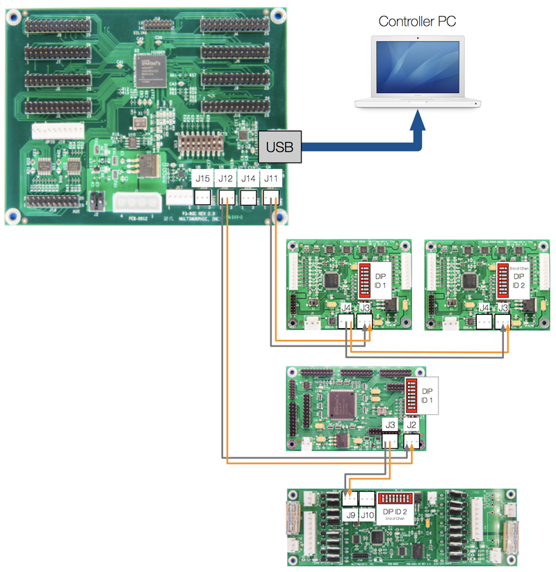
Each board is chained to the P3-ROC via multiple 2-wire cables, and each board has a unique ID set via the on-board DIP switches. Multiple boards are attached to the previous board in a daisy-chain until the chain ends at the P3-ROC as in the below diagram. The diagram is only an example - any driver board can be connected to driver serial, so you can put either PD-16s or PD-LEDs on the driver serial in any order.
Serial Cables
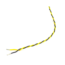
Although almost any wire over 28AWG will do to make the serial cables, It is recommended to twist the wires in a pair to help cut down on electrical interference. This can be done by hand, or by placing the ends of the wire in a drill and spinning it. Another popular option is to re-purpose inexpensive CAT5 ethernet wires as they come pre-twisted.
Wires are connected positive to positive and negative to negative. So, for the switch cable, Pin 2 (Serial Switch Data +) goes to Pin 2 on the SW-16 and so on.
DIP Switches
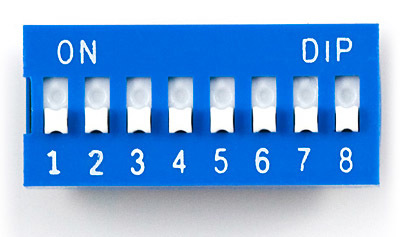
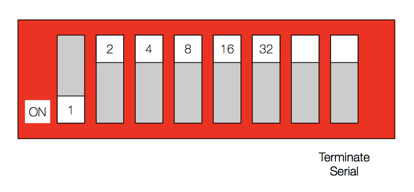
Each board includes an 8-position DIP switch, which is used to set the ID of the board in question, to terminate a chain of boards (DIP 8), and set some additional settings.
Each board needs a unique ID per serial chain - ie. you can have two Board 0s as long as they are on different chains. DIP 1-6 sets the ID in binary notation, starting at zero (All Off). So if you want to set the board ID to 5, you would set DIP 1 and 3 to On. Or if you want to set the board ID to 0, leave all six Off. If the board is the last board in the chain, set DIP 8 to On as well to terminate the serial chain. Boards connected earlier in the chain should have DIP 8 Off.
Wiring Examples
There are a number of ways to connect the P3-ROC boards to your machine but the following are some basic configurations to illustrate serial, power and device connections.
Important Note: When wiring up multiple power supplies for logic, solenoids and LEDs, it is critical to connect all grounds together at the power supplies (or use the Power Entry board) to avoid a potential floating ground issue that can easily destroy your boards.
Serial Wiring
Remember to use twisted wire to help mitigate electrical interference with the serial signal.
For Switch serial, the pinout is:
| Pin | Description |
|---|---|
| 1 | Ground |
| 2 | Serial Switch Data + |
| 3 | Serial Switch Data - |
For Driver serial, the pinout is:
| Pin | Description |
|---|---|
| 1 | Serial Driver Data + |
| 2 | Serial Driver Data - |
| 3 | Ground |
In this diagram, it shows the serial connections between the P3-ROC, two SW-16s, a PD-LED and a PD-16. The SW-16s are connected to one of the two Serial Switch connectors while the PD-LED and PD-16 are connected to one of the two Serial Driver connectors. Note how the pinouts on Switch and Driver are different.
It also shows how the DIP switches are set on each board to ID them, as well as to terminate the chain on the last board (DIP-8). For this example, the boards are numbered ID 1 and ID 2 in each chain, with the last board terminated via DIP 8.
