Driver Board functionality
PinballControllers.com Driver Boards contain circuits that turn on/off external devices, such as those commonly found on pinball machines.
Unlike with traditional pinball machine power/driver boards, multiple PinballControllers.com Driver Boards can be used at the same time in a machine. They were designed with a 2-wire RS-485 serial interface so that they can be chained together and located anywhere in the machine (in the backbox, under the playfield, or even somewhere else in the cabinet).
Each board contains a set of dipswitches, four of which are used to set a board address. Further, each board is logically divided into two banks of 8 circuits, bank A and bank B. The P-ROC, or other device controlling the chain of boards, can individually address each bank on each of the 16 possible board addresses. Refer to the documentation for each board for more details on the addressing.
Power-Driver-16 Driver Boards
The Power-Driver-16 boards contain 16 current sink circuits and can therefore control up to 16 individual features.
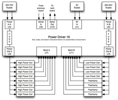
Each bank of 8 current sink circuits contains a 3-pin power input header, a fuse, a 3-pin power output header, 8 n-channel MOSFETs, and a 9-pin header used to connect external devices to the board. The power input header can accept between 5VDC and 80VDC. This power goes through the fuse and then to the power output header. All 8 devices controlled by each bank should be powered from this power output header so that the fuse protects the 8 devices from over-current conditions without affecting other circuits. The other side of the 8 devices should connect back to the 9-pin header so that the board can activate each circuit individual.
Here's a diagram of one way this board can be used:
Power-Driver-Matrix-8x8 Driver Boards
Power-Driver-Matrix-8x8 boards contain 8 current source circuits and 8 current sink circuits and are therefore good for controlling 8 columns and 8 rows, respectively, of a lamp/led matrix.
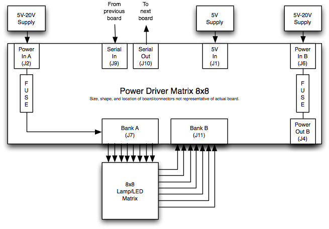
The bank of 8 current sink circuits works exactly like the bank of current sink circuits on the Power-Driver-16 boards. Each bank of 8 current source circuits contains a 3-pin power input header, a fuse, 8 p-channel MOSFETs, and a 9-pin header used to connect external devices to the board. The power input header can accept between 5VDC and 20VDC. This power goes through the fuse and then to 8 MOSFETs. The drain side of the MOSFETs are then connected to the 9-pin header from which 8 external devices or matrix columns can be powered.
Here's a diagram of one way this board can be used:


