Driver Board hardware installation
Revision as of 06:00, 8 February 2016 by Steveshoyer (talk | contribs) (Created page with "== PD-Master == * Install the Master near the P-ROC (or other controller). *Master board J8 connects to P-ROC J34 header via the 16-pin ribbon cable that came with the board....")
Contents
PD-Master
- Install the Master near the P-ROC (or other controller).
- Master board J8 connects to P-ROC J34 header via the 16-pin ribbon cable that came with the board.
- If you're not using a P-ROC, connect your controller's serial data pin to pin 1 on the Master board's ribbon cable header and at least one ground pin from your controller to an even numbered pin on ribbon cable header.
- Note, the Master board's data input pin (pin 1 on the ribbon cable header) is a 3.3V input. It is NOT 5V tolerant. If you are using a 5V controller, be sure to level translate the signal before it reaches the Master board. Simply using a current limiting resistor is NOT sufficient.
- Connect the Master board's Serial Output connector (J10) to next board's Serial Input connector (J9).
- Connect 5V to J1.
Note - These instructions also apply to the master portion of master-combo boards.
PD-16
- Connect 5V to J1.
- Connect the the Serial Input connector (J9) to previous board's Serial Ouptut connector (J10) (unless this is a master-combo board)
- Connect the the Serial Output connector (J10) to next board's Serial Input connector (J9).
- Set the address (dipswitches 4 through 1) to a unique address. Dipswitches 4:1 map to board address 3:0. Switch ON is 1, switch OFF is 0.
- Note, P-ROC drivers can be configured into driver groups for the first 8 board addresses (0-7). When using a P-ROC, boards with addresses greater than 7 must be accessed directly by software by writing the appropriate data to Module 3, Address 0xC00. Refer to the P-ROC FPGA specs for more details on the command format.
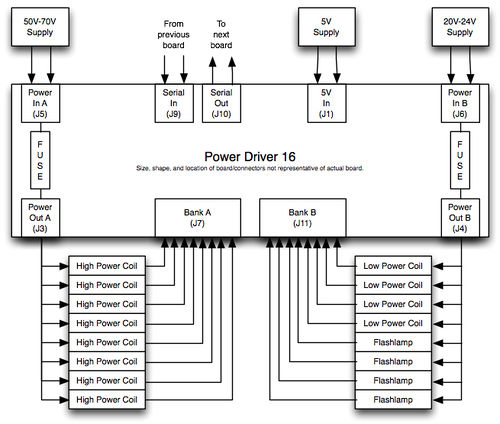
Bank A
- Connect your voltage source (5V-80V) to the Bank A Power Input connector (J5)
- Use the Bank A Power Output connector (J3) to supply power to the devices you want to control with this board/bank.
- Connect each of your devices to the desired pin in J7. J7 connects to the Bank A transistors, which complete the path to ground when activated.
- Ensure F1 has a properly rated fuse for your application
Bank B
- Connect your voltage source (5V-80V) to the Bank B Power Input connector (J6)
- Use the Bank B Power Output connector (J4) to supply power to the devices you want to control with this board/bank.
- Connect each of your devices to the desired pin in J11. J11 connects to the Bank B transistors, which complete the path to ground when activated.
- Ensure F2 has a properly rated fuse for your application
Example Illustration
PD-8x8
- Connect 5V to J1.
- Connect the the Serial Input connector (J9) to previous board's Serial Ouptut connector (J10) (unless this is a master-combo board)
- Connect the the Serial Output connector (J10) to next board's Serial Input connector (J9).
- Set the address (dipswitches 4 through 1) to a unique address. Dipswitches 4:1 map to board address 3:0. Switch ON is 1, switch OFF is 0.
- Note, P-ROC drivers can be configured into driver groups for the first 8 board addresses (0-7). When using a P-ROC, boards with addresses greater than 7 must be accessed directly by software by writing the appropriate data to Module 3, Address 0xC00. Refer to the P-ROC FPGA specs for more details on the command format.
Bank A
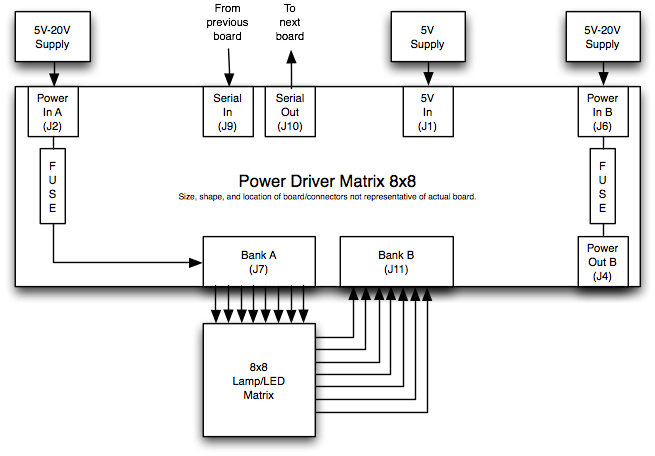
- Connect your voltage source (5V-20V) to the Bank A Power Input connector (J5)
- Use the Bank A Power Output connector (J3) to supply power to the devices you want to control with this board/bank.
- Note: If using this board to drive a lamp/led matrix, leave J3 unconnected.
- Connect each of your devices to the desired pin in J7. J7 connects to the Bank A transistors, which complete the path to ground when activated.
- Note: If using this board to drive a lamp/led matrix, connect J7 to the anode side of your LED matrix (or the input power side of your lamp matrix).
- Ensure F1 has a properly rated fuse for your application
Bank B
- Connect your voltage source (5V-80V) to the Bank B Power Input connector (J6)
- Use the Bank B Power Output connector (J4) to supply power to the devices you want to control with this board/bank.
- Note: If using this board to drive a lamp/led matrix, leave J4 unconnected.
- Connect each of your devices to the desired pin in J11. J11 connects to the Bank B transistors, which complete the path to ground when activated.
- Note: If using this board to drive a lamp/led matrix, connect J11 to the cathode side of your LED matrix (or the return side of your lamp matrix).
- Ensure F2 has a properly rated fuse for your application
Example Illustration
Cabling Guide
Connectors
These boards use the following molex connectors:
| Molex Connectors | |
|---|---|
| 0.100" | 0.156" |
| 2-pin: J9 - Serial In | 2-pin: J1 - 5V |
| 2-pin: J10 - Serial Out | 3-pin: J2 - Bank A Source In |
| 3-pin: J3 - Bank A Sink Out | |
| 3-pin: J4 - Bank B Out | |
| 3-pin: J5 - Bank A Sink In | |
| 3-pin: J6 - Bank B In | |
| 9-pin: J7 - Bank A | |
| 9-pin: J11 - Bank B | |
- Note: Not all connectors are used on all boards.
Tips
- Get a good crimp tool. Crimping a lot of pins with a hard to use tool isn't fun!
- Buy connector housings with ramps. Not only do they hold the header in place, but they also make it obvious which way to plug on the header.
- Use keying plugs on the key pins. The board connector's use different key patterns to differentiate the various types of connections (ie. power in vs power out). Using keying plugs in your connector housings will help you avoid accidentally plugging housings onto the wrong headers.
- Buy a few extra housings with the largest number of pins you foresee needing. You can always cut them down if you ever need smaller ones.
Vendors
Molex connectors/pins/housings: Great Plains Electronics*, Digikey, Mouser
- Great Plains Electronics primarily supports pinball hobbyists. His prices are comparable (and sometimes lower) than Digikey and Mouser. It's also much easier to browse his selection to find the most appropriate parts.


