Modifying a WPC-95 board for Audio Input old
Revision as of 06:10, 8 February 2016 by Steveshoyer (talk | contribs) (Created page with "NOTE: This modification, as described on this page, is not universal. Once modified in this manner, the board does not work for regular WPC95 system use until un-modified. I...")
NOTE: This modification, as described on this page, is not universal. Once modified in this manner, the board does not work for regular WPC95 system use until un-modified. It would be possible to do the modification with some built in switches to allow changing back and forth, but these directions do not provide details on that.
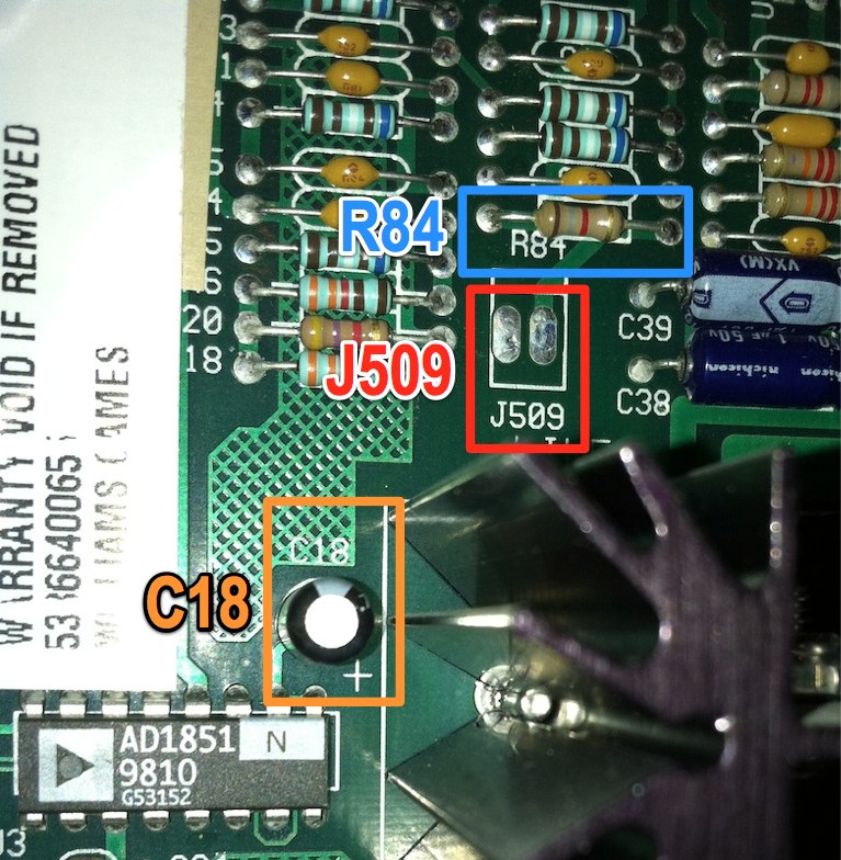
Refer to the image below for the location of the items mentioned.
Contents
Install a pin header at J509
- Find connector J509 (the component is probably not populated on your board).
- This is where a line-out connector can go. We're going to reuse this as our line-in.
- Install a 2-pin 0.100" molex (or similar type) header/connector.
- With the board facing in such a way that the J509 is right side up, pin 1 is on the right.
Remove Resistor R84
- Find resistor R84.
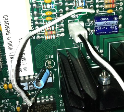
- You'll remove this completely. In this example, it is then used as a jumper point to connect to C18.
Connect J509 to the amp
- Find capacitor C18
- This may be a bit tricky to do with the present cap - but you have to pull the positive leg out of the board, leave the negative leg in.
- Alternately, remove C18 and get a new 4.7uF cap so you have longer legs for easier connection.
- With the negative side connected to the board, you'll need to connect your audio in to the positive side.
- In this example, a jumper wire goes FROM the point where pin 1 from J509 connects to the (now removed) R84 TO the positive leg of C18 (white wire)
Create a cable to hook things up
- You can now create a cable to go between your computer and your new line in.
- If you're using a stereo source, you'll want to wire them together via 1k resistors before connecting to pin 1 of your line in connector (pin 2 is ground). crude diagaram
Diagram: The board before modification:


