OPP
Contents
Open Pinball Project
The Open Pinball Project (OPP) was started in 2012 as a resource for pinball makers to have an inexpensive, fully open sourced project for controlling custom pinball machines. It is currently on a second generation design and has had a successful Kickstarter run of boards and components currently in the hands of makers all over the world.
Hardware
The OPP hardware is made up of three main components:
- The Processor board is a Cypress Semiconductor CY8CKIT-049-42XX PSoC prototyping board that can be purchased from Mouser or Digikey.
- The Interface board allows communications between Processor boards via a custom serial communications protocol.
- The Wing boards allow the control of solenoids, lamps, LEDs or input from switches.
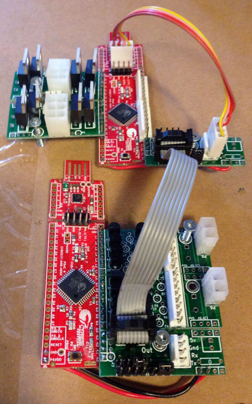
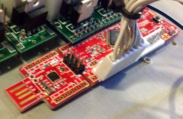
The following is an example of some fully assembled and wired OPP Processors with Wing boards.
Processor Boards
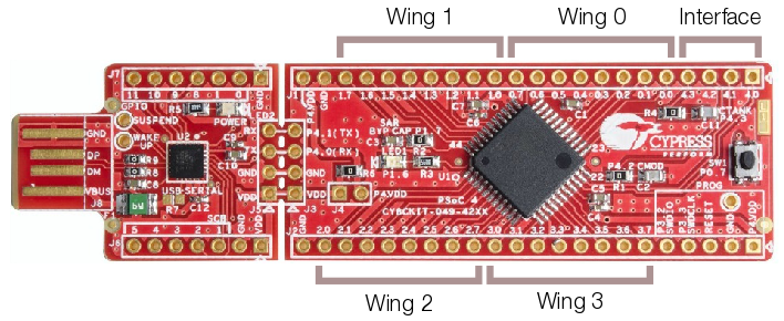
The Processor board can have up to four Wing boards controlling solenoids, incandescent lamps, or allowing input for switches. The Wing boards themselves can be combined in any configuration, so a single Processor board can support up to 16 solenoids, 32 switch inputs or 32 lamps. Each Wing board uses eight pins while the Interface board uses four.
All other pins are unused, except on the first board in the chain where the USB plug from the host controller is connected to the Interface board to provide power and serial connections for the other Processors in the chain.
The Processor itself does not run game rules or other game logic - a Controller like Mission Pinball running on a separate PC is still required to handle scoring and other game logic and to fire coils and light lamps as needed. The Processor simply provides the physical connection to playfield devices.
Serial Link
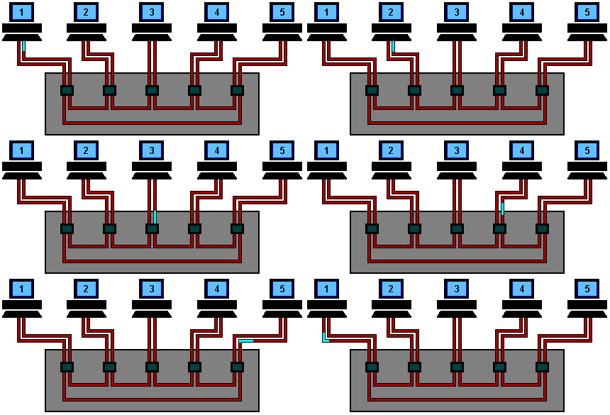
The 8-pin ribbon cable serial link between boards works in a similar fashion to a Token Ring network, where each Processor receives messages via the serial line, looks for commands addressed to its ID, removes that command from the message and then passes the remaining message to the next Processor in the chain. The Processor then performs the requested action such as firing a solenoid or turning on a lamp. Switch events are passed back to the primary board and up to the host controller.
The following image gives a visual idea of how messages flow between the Processors:
Like in the above image, each Processor assigns itself an ID on power-up based on its position in the serial chain, so boards do not need to be pre-programmed with IDs and can be placed anywhere in the chain, with the caveat that inserting a new card in the middle of a chain will change the ID of every board after it, which will change the hard-coded numbering in controllers like MPF.
Solenoid Wing
The Solenoid wing uses FQP13N06L MOSFETs to control up to four individual coils via a ground sink method, where the coils themselves are wired to the positive side of the high voltage power supply and the MOSFET provides a ground path when activated, firing the coil.
Standard coil voltages are 24V to 48V and upwards of 10A of current.
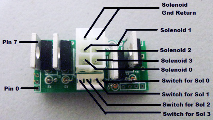
There are two connectors on the Solenoid wing - the larger 6-pin has four pins for the coil connections and two for ground. The 4-pin connector is for direct control switch inputs, for devices like slingshots or pop bumpers that require fast response to switch hits in order to fire coils.
Note that the OPP boards support direct control switch programming, so that such devices can be configured in the firmware itself, and the 4-pin connector can cause some packaging issues, so it is recommended to leave the 4-pin connector out when building the boards unless you need it specifically.
However, using the direct switches allows the game to be tested without a host controller, since pop bumpers, slingshots and flippers will work without it.
Incandescent Wing
The Incandescent wing uses 2N7000 MOSFETs to control up to eight direct wired incandescent lamps via the same ground sink method as the coils.
Lamps require a high current 12V power supply as each 6.3V bulb needs about a 1/4A to fully light.
Direct wired means that each lamp is wired up and controlled individually via the 8-pin connector, rather than in the Matrix style that most commercial pinball machines used until recently.
The other 2-pin connector is for the Ground connection.
Switch Wing
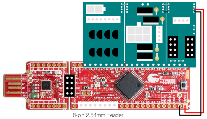
Switches are wired directly to the Processor board via an 8-pin 2.54mm locking header.
Unlike the Solenoid and Incandescent wings, the Switch wing is set up as High-side, where the switch pins are at 5V and playfield and cabinet switches are tied to Ground, so that when a switch is activated, the pins are grounded and the switch is considered 'closed'. It is set up this way since the Processor pins have a Pull-Up resistor on them that is tied to 5V.
So instead of providing a ground path, switches are proving a positive voltage path.
Interface Wing
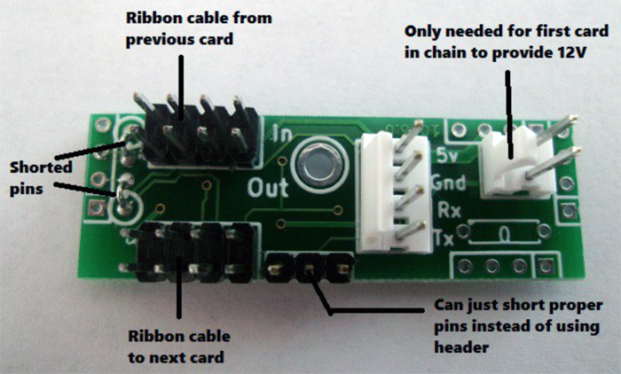
The Interface wing has no transistors or other electronic parts on it other than connectors. Its purpose is to distribute low voltage power (primarily 5V) and serial connections between each Processor board.
Before You Start
Determine Your Board Layout
Prior to sourcing and purchasing the OPP boards and components, you need to know how many solenoids, lamps and switches you need to support, and a general layout of where you will put boards and how they will be mounted.
For example, a custom game might require 31 inputs, 10 solenoids (with 10 direct inputs), and 43 incandescent bulbs. This could be accomplished with four Processor boards with four Interface wings, three Solenoid wings, six Incandescent wings and five Switch wings. Technically this is more than strictly required as the Processor boards could handle a denser configuration, but it cuts down on the total wiring required, saving significant time and money.
Alternatively, if you're converting a Williams Jokerz machine, It has 19 solenoids (includes direct inputs), 39 inputs and 63 incandescent bulbs (which includes 9 flashers). A possible layout for that is five Processor boards with five Interface wings, four Solenoid wings, eight Incandescent wings and five Switch wings.
Once the total number of Processor and Wing boards has been determined, parts can be ordered.
Power Supply Needs
When running solenoids and lamps, you'll need three voltages: 5V 3A for logic, 12V 10A for lamps and 24V to 48V 10A for solenoids. See the Power Supply section for details of what is available.
Getting Blank Boards
The OPP site itself does not sell blank boards and there currently is no one selling fully populated and tested boards. However, given the open source nature of the project, there are multiple ways to get the blanks.
The easiest is to order boards from MezelMods as they offer blanks for a very reasonable $1US per board.
The next option is to create Gerber files from the KiCad files located in the OPP SVN repository. For this you'll need to download KiCad, which is a printed circuit board design tool that was used to create the OPP boards. Once you have the Gerber files, they can be uploaded to a number of low-cost PCB manufacturers such as:
Each PCB maker has plusses and minuses that are too involved to go into in this wiki, but SeeedStudio has good prices and fast shipping.
Getting PCBs made can be a fairly advanced process, so it is recommended to simply purchase the already-made boards via MezelMods. They also offer additional parts that are less expensive than purchasing through Digikey or Mouser such as the FC-8P connectors and the 1x40 2.54 mm headers.
Getting Components
Once you have the bare boards, they will need to be fully populated with components, which are not included - they will need to be sourced separately. The following is a Bill of Materials for each Processor and Wing board.
Processor Board
| Quantity | Mouser Part # | Description | Price Est. |
|---|---|---|---|
| 1 | 727-CY8CKIT-049-42XX | Cypress Semiconductor PSoC 4200 Prototyping Kit | $3.98/ea |
| 1 | 649-68602-108HLF | 2 x 4 position 2.54 mm Header | $0.45/ea |
| 2 | 571-9-146278-0 | 40-pin 2.54 mm Header | $2.51/ea |
| 2 | SX1100-B | 2.54 mm Jumper | $0.10/ea |
Note: The 40-pin header is available much cheaper in larger quantities from eBay - search for "1x40 2.54mm header".
Solenoid Wing
| Quantity | Mouser Part # | Description | Price Est. |
|---|---|---|---|
| 4 | 512-FQP13N06L | FQP13N06L MOSFET | $0.67/ea |
| 4 | 603-CFR-12JR-5210K | 10K Ohm Resistor (1/6W 5%) | $0.02/ea |
| 1 | 538-35317-0620 | Molex 6-pin 4.2 mm Mini-Fit Header | $0.28/ea |
| 10 | 538-39-00-0039 | Molex Crimp-Style 4.2 mm 24-18AWG Female Pins | $0.19 |
| Parts Needed ONLY If Adding Direct Switches | |||
| 6 | 538-08-50-0136 | Molex Crimp-Style 2.54 mm KK Pins | $0.13/ea |
| 1 | 538-22-01-2047 | Molex 4-Pin 2.54 mm Housing | $0.17/ea |
Note: The total number of crimp-style pins included in the BoM is higher than actually needed to account for extras if needed.
Incandescent Wing
| Quantity | Mouser Part # | Description | Price Est. |
|---|---|---|---|
| 8 | 512-2N7000TA | MOSFET 60V N-Channel | $0.33/ea |
| 1 | 538-39-28-1023 | Molex 2-pin 4.2 mm Housing | $0.56/ea |
| 3 | 538-39-00-0039 | Molex Crimp-Style 4.2 mm 24-18AWG Female Pins | $0.19/ea |
| 1 | 571-6404548 | 8-pin 2.54 mm Header | $0.45/ea |
| 1 | 538-22-01-2087 | Molex 8-pin 2.54 mm Housing | $0.32/ea |
| 10 | 538-08-50-0136 | Molex Crimp-Style 2.54 mm KK Pins | $0.13/ea |
Switch Wing
| Quantity | Mouser Part # | Description | Price Est. |
|---|---|---|---|
| 1 | 571-6404548 | 8-pin 2.54 mm Header | $0.45/ea |
| 1 | 538-22-01-2087 | Molex 8-pin 2.54 mm Housing | $0.32/ea |
| 10 | 538-08-50-0136 | Molex Crimp-Style 2.54 mm KK Pins | $0.13/ea |
Note: The Switch wing is just the 8-pin headers soldered directly to the Processor board with the upright lock facing out from the board.
Interface Wing
| Quantity | Mouser Part # | Description | Price Est. |
|---|---|---|---|
| 2 | 649-68602-108HLF | 2 x 4 position 2.54 mm Header | $0.45/ea |
| 2 | 538-22-01-2047 | Molex 4-Pin 2.54 mm Housing | $0.17/ea |
| 10 | 538-08-50-0136 | Molex Crimp-Style 2.54 mm KK Pins | $0.13/ea |
| 2 | eBay (search "FC-8P") | FC-8P IDC Socket 2.54 mm | ~ $0.10/ea |
| ~10ft | eBay (search "8 pin IDC cable") | 8-pin IDC Flat cable | ~$1/ft |
Note: Neither Mouser nor Digikey have FC-8P connectors or flat cable in stock, so eBay is the best source for these parts.
Assembly
Once all the boards and the components are available, you can begin assembly.
Processor Board Assembly
As delivered, the Cypress PSoC 4200 board needs to have two traces on the USB to Serial portion of the board cut - the TX and RX lines. Use an X-Acto knife to cut the thin traces on both sides of the board and use a Multimeter to test between the two through holes to confirm there is no connectivity. This is important to prevent crosstalk on the serial lines.
After the lines are cut, the headers (or lock connectors if being used for switches) can be soldered in, along with the 2x4 header between the USB-to-Serial interface and the main board.
Interface Wing Assembly
The main parts of the Interface wing are the two 2x4 headers for the serial connection and the 4-pin locking header that is used on the first Processor board to bring the Serial output from the USB-to-Serial card into the Interface wing. The 4-pin header is only required for the first Processor board in the chain, and can be left out when building the wing for subsequent boards.
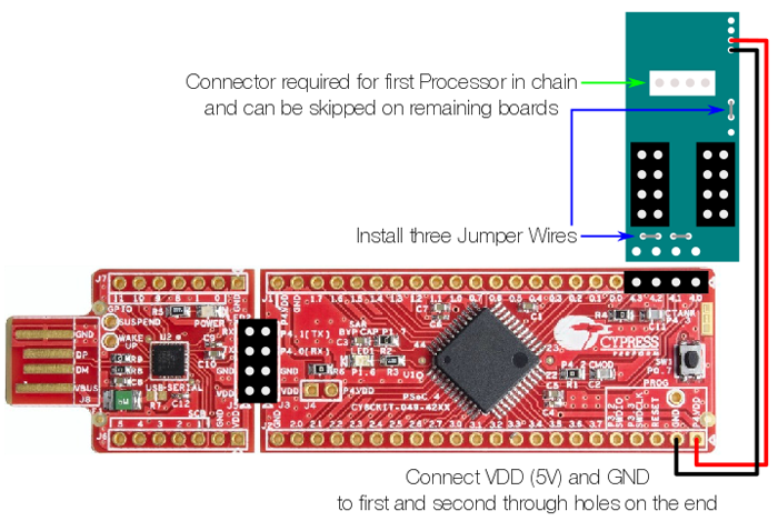
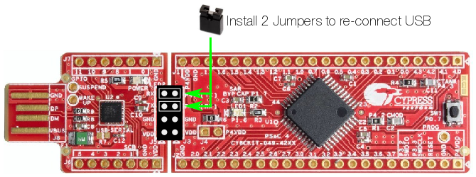
It is best to start with the smallest components and work up - solder the two termination jumpers (marked as R2 and R3) and the serial connector enable jumper as depicted in the diagram, then the 2x4 headers, and finally the 4-pin header if needed.
Once assembled, the Interface board can be soldered to the Processor board on the last four pins marked 4.0 through 4.3 as per the diagram.
The final step is to connect VDD and GND to the Interface wing by soldering wire from the Processor board to the Interface wing as per the diagram - GND to Pin 1 and 5V to Pin 2. This is required to power all the downstream Processor boards as none of them will be plugged into the USB connector which normally provides power. The 8-pin ribbon cable used for serial communications also provides 5V and ground connections.
Solenoid Wing Assembly
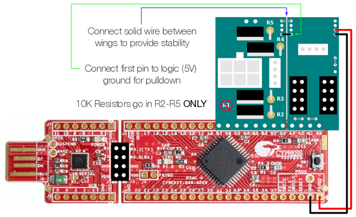
The parts for the Solenoid wing are the four MOSFETs, four 10K Resistors, a 2x3 header and a 4-pin locking header. If you are not using the direct switch capabilities of the Solenoid wing, it is recommended to leave the 4-pin out of the build as it causes some packaging issues when placing wings next to each other, as the 2x3 header sticks off the end of the board slightly and makes contact with the 4-pin header on the adjacent wing.
As with the Interface wing, start with the smallest components and work upwards - resistors, MOSFETs then headers. The 2x3 header should be installed with the locking tab facing "up" as in the above diagram.
After assembly, it can be soldered in the appropriate spot on the Processor board. It is recommended to place Solenoid boards in the Wing 0 and Wing 1 positions as this allows a short jumper to connect the logic (5V) ground wiring for the pulldown, as well as slightly better fitment due to the chip packaging on the Processor boards. However, it is not a requirement - Solenoid wings can be placed in any position, as long as the pulldown ground is properly wired.
After soldering the Solenoid wing to the Processor board, use a solid wire jumper to tie it and the Interface board together on the very end through holes. This is a purely physical connection that helps add stability to the board - there is no electrical connection on those holes. A good source for a jumper wire are the leftover legs from the resistors after they've been soldered in and cut to length.
Incandescent Wing Assembly
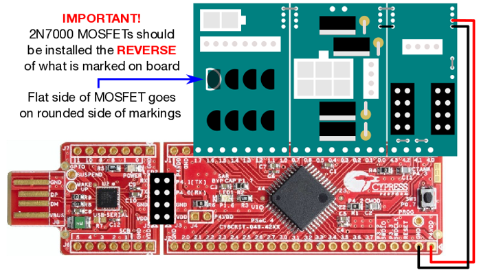
The through-hole Incandescent wing parts are eight 2N7000 MOSFETs, an 1x8 locking header for lamp connections and a 2-pin header for the 12V ground connection. No resistors are required, so all resistor spots are left empty.
NOTE: As the board was originally designed for BS170 transistors, the screened artwork reflects the pinout for that part, but the pinout is reversed for the 2N7000, so it is critically important to install the MOSFETs in the REVERSED orientation from the artwork.
The tab for the 2-pin header should face inwards towards the center of the board.
Once assembly is complete and the wing is installed on the Processor, a solid wire jumper should be installed on the end holes to provide stability. As with all wing boards other than the Interface board, the Incandescent wing can be installed in any of the four positions.
Switch Wing Assembly
There is no physical wing board required for the Switch wing - it consists entirely of a single 8-pin 2.54mm locking header connected directly to the Processor board.
Programming Firmware
Besides the hardware design, OPP also provides the firmware for running the Processors . It is available for download via the SVN repo.
RX/TX Jumpers
As part of the initial board setup, the RX/TX traces were cut on the Processor board. In order to communicate with a board, jumpers will need to be installed across the two serial pins on the USB-to-Serial portion of the board.
Determine your USB Device
In order to talk to the Processor, a device driver will likely need to be installed on your host computer. Cypress offers drivers for Windows, Linux and Mac.
Once installed, plugging in the Processor should result in a device being mounted on your system, with an associated serial device - a COM port on Windows or a tty or cu file in the /dev directory for Linux and Mac.
To determine the port, check the syslog on Mac/Linux or the System Console on WIndows
Whatever the device name is, save it as it will be used for programming the firmware and all future communication with the Processor boards.
cyflash
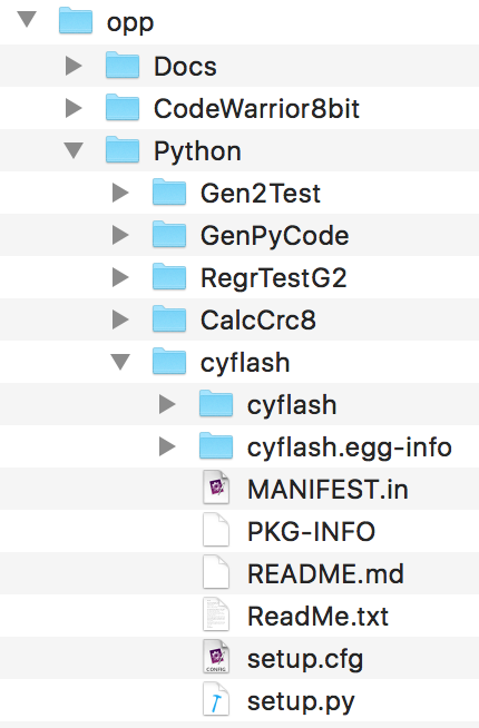
cyflash is a Python utility provided by Cypress to upload bytecode to the PSoC. It is included as part of the SVN repo under the Python directory. You will need to download the repo to your host controller or whatever computer is being used for setup.
How the firmware is uploaded depends on which OS you use - Windows, Linux or Mac. Linux and Mac are a bit simpler as they already have the correct version of Python installed by default. For Windows, download the Latest Version of Python 2.7 and install it in the C:\Python27 directory (which should be the default).
Once Python is installed, from the command line, change into the Python/cyflash/ directory. The cyflash utility can be envoked with the following parameters:
Linux/Mac
python -m cyflash.__main__ --serial /dev/[serial-device] --serial_baudrate 115200 ../../Creator/Gen2Images/Gen2.rev0.2.0.0.cyacd
Windows
c:\Python27\Python.exe -m cyflash.__main__ --serial COM[serial-device] --serial_baudrate 115200 ..\..\Creator\Gen2Images\Gen2.rev0.2.0.0.cyacd
Before running the command, you must put the Processor into bootloader mode. Plug the board in while holding down the small switch at the end of the board, which will cause the blue LED to flash rapidly. Once this is done, press [Enter] and the cyflash utility should begin to download the firmware. When it is complete, the board should reboot and the LED stop flashing.
Gen2Test
Gen2Test is the OPP utility used to inventory, erase and save the board configuration prior to using it with the host controller. Using an external Python script as a config file, it sets all the Wing board types that are connected to the Processor. Even if you use a framework like MPF, it is a good idea to configure each board separately.
Once the firmware is installed, from the command line change into the Python/Gen2Test directory.

