Difference between revisions of "OPP"
(→Troubleshooting) |
(→Firmware) |
||
| (27 intermediate revisions by 4 users not shown) | |||
| Line 2: | Line 2: | ||
The [https://openpinballproject.wordpress.com/ Open Pinball Project (OPP)] was started in 2012 as a resource for pinball makers to have an inexpensive, fully open sourced project for controlling custom pinball machines. It is currently on a second generation design and has had a successful Kickstarter run of boards and components currently in the hands of makers all over the world. | The [https://openpinballproject.wordpress.com/ Open Pinball Project (OPP)] was started in 2012 as a resource for pinball makers to have an inexpensive, fully open sourced project for controlling custom pinball machines. It is currently on a second generation design and has had a successful Kickstarter run of boards and components currently in the hands of makers all over the world. | ||
| + | |||
| + | |||
| + | '''In 1Q 2020, it was decided to switch to a new layout, due to the unavailability of processor boards. | ||
| + | |||
| + | '''This page should be considered as a Work In Progress. ''' | ||
| + | |||
| + | Archives on the previous layout can be found on [[OPP-Cypress|Archives of OPP]]'''. | ||
| + | More details on this change are available in the [https://groups.google.com/forum/#!topic/mpf-users/QVQsO6JjID8 MPF Users forum]. | ||
== Hardware == | == Hardware == | ||
| Line 7: | Line 15: | ||
The '''OPP''' hardware is made up of three main components: | The '''OPP''' hardware is made up of three main components: | ||
| − | * The '''Processor''' board is a [ | + | * The '''Processor''' board is a [https://www.st.com/content/st_com/en/products/microcontrollers-microprocessors/stm32-32-bit-arm-cortex-mcus/stm32-mainstream-mcus/stm32f1-series/stm32f103/stm32f103c8.html STM32F103C8 ] prototyping board that can be purchased from '''TODO'''. |
| − | |||
* The '''Wing''' boards allow the control of solenoids, lamps, LEDs or input from switches. | * The '''Wing''' boards allow the control of solenoids, lamps, LEDs or input from switches. | ||
| − | + | * The '''Power Filter Board''' to allow the use of inexpensive switching power supplies. | |
| − | |||
| − | |||
The following is an example of some fully assembled and wired OPP ''Processors'' with ''Wing'' boards. | The following is an example of some fully assembled and wired OPP ''Processors'' with ''Wing'' boards. | ||
| − | + | ''Pictures to be added'' | |
=== Processor Boards === | === Processor Boards === | ||
| − | The ''Processor'' board can have up to four ''Wing'' boards controlling solenoids, incandescent lamps, or allowing input for switches. The ''Wing'' boards themselves can be combined in any configuration, so a single ''Processor'' board can support up to 16 solenoids (with 16 direct switch inputs), 32 switch inputs or 32 lamps. Each ''Wing'' board uses eight pins | + | The ''Processor'' board can have up to four ''Wing'' boards controlling solenoids, incandescent lamps, or allowing input for switches. The ''Wing'' boards themselves can be combined in any configuration, so a single ''Processor'' board can support up to 16 solenoids (with 16 direct switch inputs), 32 switch inputs or 32 lamps. Each ''Wing'' board uses eight pins. |
| − | |||
| − | |||
| − | |||
| − | |||
| − | |||
| − | |||
| − | |||
| − | |||
| − | |||
| − | |||
| − | |||
| − | |||
| − | |||
| − | |||
| − | |||
| − | |||
| − | |||
| − | |||
| − | + | All other pins are unused. | |
| − | + | ''Pictures to be added'' | |
| − | The '' | + | The ''Processor'' itself does not run game rules or other game logic - a ''Controller'' like [https://missionpinball.org/ Mission Pinball] running on a separate PC is still required to handle scoring and other game logic and to fire coils and light lamps as needed. The ''Processor'' simply provides the physical connection to playfield devices. However, coils can automatically be fired by the activation of their related direct switch input to allow a "white wood" mode that does not require a controller. |
| − | |||
| − | |||
| − | |||
| − | |||
=== Solenoid Wing === | === Solenoid Wing === | ||
| − | The ''Solenoid'' wing uses | + | The ''Solenoid'' wing uses MOSFETs to control up to four individual coils via a ''ground sink'' method, where the coils themselves are wired to the positive side of the high voltage power supply and the MOSFET provides a ground path when activated, firing the coil. |
Standard coil voltages are '''24V''' to '''48V''' and upwards of '''10A''' of current. | Standard coil voltages are '''24V''' to '''48V''' and upwards of '''10A''' of current. | ||
| Line 62: | Line 45: | ||
==== Special Solenoids ==== | ==== Special Solenoids ==== | ||
| − | For devices like flippers, slingshots or pop bumpers that require fast response to switch hits in order to fire coils, the ''Solenoid'' wing has four '''Direct Inputs''' that are used to directly activate the associated coil without the computer needing to detect a switch closure and send a solenoid activation command. | + | For devices like flippers, slingshots or pop bumpers that require fast response to switch hits in order to fire coils, the ''Solenoid'' wing has four '''Direct Inputs''' that are used to directly activate the associated coil without the computer needing to detect a switch closure and send a solenoid activation command. These are known as ''Autofire'' coils. This direct activation can also be cancelled if needed by the Controller where theses switches can be considered as normal switches. |
As of this writing, '''OPP''' only supports ''Autofire'' coils using the direct inputs or switch inputs on the '''same controller as the solenoid itself'''. This means you can't have an ''Autofire'' switch on another controller. | As of this writing, '''OPP''' only supports ''Autofire'' coils using the direct inputs or switch inputs on the '''same controller as the solenoid itself'''. This means you can't have an ''Autofire'' switch on another controller. | ||
| Line 72: | Line 55: | ||
=== Incandescent Wing === | === Incandescent Wing === | ||
| − | The ''Incandescent'' wing uses | + | The ''Incandescent'' wing uses MOSFETs to control up to eight direct wired incandescent lamps via the same ''ground sink'' method as the coils. |
Lamps require a high current '''6.3V''' power supply as each bulb needs about '''.25A''' at full brightness. | Lamps require a high current '''6.3V''' power supply as each bulb needs about '''.25A''' at full brightness. | ||
| Line 81: | Line 64: | ||
The other 2-pin connector is for the '''Ground''' connection. | The other 2-pin connector is for the '''Ground''' connection. | ||
| + | |||
| + | Note: This picture shows the MOSFETs reversed from the silkscreen which is required if using 2N7000TA MOSFETs which should be avoided. If using the BS-170 MOSFETs, the silkscreen matches the MOSFET orientation. Careful! | ||
=== Switch Wing === | === Switch Wing === | ||
| Line 86: | Line 71: | ||
Switches are wired directly to the ''Processor'' board via an 8-pin 2.54mm locking header. | Switches are wired directly to the ''Processor'' board via an 8-pin 2.54mm locking header. | ||
| − | + | ''Picture to be added'' | |
Unlike the ''Solenoid'' and ''Incandescent'' wings, the ''Switch'' wing is set up as ''High-side'', where the switch pins are at '''5V''' and playfield and cabinet switches are tied to '''Ground''', so that when a switch is activated, the pins are grounded and the switch is considered 'closed'. It is set up this way since the ''Processor'' pins have a '''Pull-Up''' resistor on them that is tied to 5V. | Unlike the ''Solenoid'' and ''Incandescent'' wings, the ''Switch'' wing is set up as ''High-side'', where the switch pins are at '''5V''' and playfield and cabinet switches are tied to '''Ground''', so that when a switch is activated, the pins are grounded and the switch is considered 'closed'. It is set up this way since the ''Processor'' pins have a '''Pull-Up''' resistor on them that is tied to 5V. | ||
| Line 108: | Line 93: | ||
| − | The power filter board can be configured to provide bulk capacitance for one or two power supplies. If two power supplies are needed, a second P-Channel MOSFET and inrush current limiter must be bought. | + | The power filter board can be configured to provide bulk capacitance for one or two power supplies. If two power supplies are needed, a second P-Channel MOSFET and inrush current limiter (NTC) must be bought. |
If the ability to enable/disable the high power voltage isn't needed, a jumper can be added instead of the P-channel MOSFETs. | If the ability to enable/disable the high power voltage isn't needed, a jumper can be added instead of the P-channel MOSFETs. | ||
| Line 171: | Line 156: | ||
==== Processor Board ==== | ==== Processor Board ==== | ||
| + | |||
| + | OPP has moved away from using PSOC4200 boards since they are no longer available. The firmware has been ported to use STM32F103C8T6 blue pill boards that are even cheaper. These boards can easily be purchased from either Ebay or Aliexpress. A programmer (ST Link-V2) is needed to program the firmware. Luckily, these are typically sold from the same vendors. In either Ebay or Aliexpress search for STM32F103C8T6. If using Aliexpress insure that the seller has sold at least a couple of hundred boards. Processor boards and the programmer are about $1.50 or $2.00 each plus shipping if willing to wait for shipping from China. | ||
{| class="wikitable" | {| class="wikitable" | ||
| Line 181: | Line 168: | ||
|- | |- | ||
| 1 | | 1 | ||
| − | | | + | | Ebay or Aliexpress |
| − | + | | STM32F103C8T6 blue pill | |
| − | + | | $2.00/ea | |
| − | |||
| − | |||
| − | |||
| − | |||
| − | | | ||
| − | | $ | ||
| − | |||
| − | |||
| − | |||
| − | |||
| − | |||
| − | |||
| − | |||
| − | |||
| − | |||
| − | |||
| − | |||
| − | |||
| N/A | | N/A | ||
|} | |} | ||
| − | '''Note:''' The | + | '''Note:''' The STM32F103C8T6 processor boards come with the headers so there is no need to purchase them anymore. |
==== Solenoid Wing ==== | ==== Solenoid Wing ==== | ||
| Line 217: | Line 186: | ||
|- | |- | ||
| 4 | | 4 | ||
| − | | [ | + | | [https://www.mouser.com/_/?keyword=IRL540NPBF 942-IRL540NPBF] |
| − | | | + | | N-Channel MOSFET 100V 36A |
| − | | $0. | + | | $0.71/ea |
|- | |- | ||
| 4 | | 4 | ||
| − | | [ | + | | [https://www.mouser.com/_/?keyword=CFR-12JR-5210K 603-CFR-12JR-5210K] |
| 10K Ohm Resistor (1/6W 5%) | | 10K Ohm Resistor (1/6W 5%) | ||
| $0.02/ea | | $0.02/ea | ||
|- | |- | ||
| 1 | | 1 | ||
| − | | [ | + | | [https://www.mouser.com/_/?keyword=35317-0620 538-35317-0620] |
| Molex 6-pin 4.2 mm Mini-Fit Header | | Molex 6-pin 4.2 mm Mini-Fit Header | ||
| $0.28/ea | | $0.28/ea | ||
|- | |- | ||
| 6 | | 6 | ||
| − | | [ | + | | [https://www.mouser.com/_/?keyword=39-00-0039 538-39-00-0039] |
| Molex Crimp-Style 4.2 mm 24-18AWG Female Pins | | Molex Crimp-Style 4.2 mm 24-18AWG Female Pins | ||
| $0.19/ea | | $0.19/ea | ||
|- | |- | ||
| 1 | | 1 | ||
| − | | [ | + | | [https://www.mouser.com/_/?keyword=39-01-2065 538-39-01-2065] |
| Molex 6-pin 4.2 mm Mini-Fit Housing | | Molex 6-pin 4.2 mm Mini-Fit Housing | ||
| $0.52/ea | | $0.52/ea | ||
| Line 244: | Line 213: | ||
|- | |- | ||
| 1 | | 1 | ||
| − | | [ | + | | [https://www.mouser.com/_/?keyword=640454-4 640454-4] |
| 4-pin Polarized 2.54 mm Header | | 4-pin Polarized 2.54 mm Header | ||
| $0.12/ea | | $0.12/ea | ||
|- | |- | ||
| 6 | | 6 | ||
| − | | [ | + | | [https://www.mouser.com/_/?keyword=08-50-0136 538-08-50-0136] |
| Molex Crimp-Style 2.54 mm KK Pins | | Molex Crimp-Style 2.54 mm KK Pins | ||
| $0.13/ea | | $0.13/ea | ||
|- | |- | ||
| 1 | | 1 | ||
| − | | [ | + | | [https://www.mouser.com/_/?keyword=22-01-2047 538-22-01-2047] |
| Molex 4-Pin 2.54 mm Housing | | Molex 4-Pin 2.54 mm Housing | ||
| $0.17/ea | | $0.17/ea | ||
| − | |||
| − | |||
| − | |||
| − | |||
| − | |||
| − | |||
| − | |||
|} | |} | ||
'''Note:''' The total number of crimp-style pins included in the BoM is higher than actually needed to account for re-crimping. | '''Note:''' The total number of crimp-style pins included in the BoM is higher than actually needed to account for re-crimping. | ||
| + | |||
| + | '''Note 2:''' Since the price of the higher current (IRL540) MOSFETs have dropped, it now makes sense just to use these MOSFETs for all configurations. | ||
==== Incandescent Wing ==== | ==== Incandescent Wing ==== | ||
| Line 278: | Line 242: | ||
|- | |- | ||
| 8 | | 8 | ||
| − | | [http://www.mouser.com/ProductDetail/Fairchild-Semiconductor/ | + | | [http://www.mouser.com/ProductDetail/Fairchild-Semiconductor/BS170 512-BS170] |
| − | | | + | | N-Channel MOSFET 60V 500mA |
| − | | $0. | + | | $0.39/ea |
|- | |- | ||
| 1 | | 1 | ||
| Line 312: | Line 276: | ||
| $0.13/ea | | $0.13/ea | ||
|- | |- | ||
| − | |colspan=4| | + | |colspan=4|Lower Current alternative MOSFET that should be avoided |
|- | |- | ||
| 8 | | 8 | ||
| − | | [http://www.mouser.com/ProductDetail/Fairchild-Semiconductor/ | + | | [http://www.mouser.com/ProductDetail/Fairchild-Semiconductor/2N7000TA/ 512-2N7000TA] |
| − | | N-Channel | + | | MOSFET 60V N-Channel |
| − | | $0. | + | | $0.33/ea |
|} | |} | ||
| Line 348: | Line 312: | ||
==== Interface Wing ==== | ==== Interface Wing ==== | ||
| + | |||
| + | Interface wing boards are no longer needed if using the newer STM32F103 processor boards. Each STM32F103 is connected to the host computer with a USB cable. This eliminates the need for the interface board. | ||
{| class="wikitable" | {| class="wikitable" | ||
| Line 522: | Line 488: | ||
<code>(Power Supply Voltage * 100K) / Processor Voltage - 100K = Resistor</code> | <code>(Power Supply Voltage * 100K) / Processor Voltage - 100K = Resistor</code> | ||
| + | |||
| + | ==== Solenoid Plank ==== | ||
| + | {| class="wikitable" | ||
| + | |- | ||
| + | ! Quantity | ||
| + | ! Mouser Part # | ||
| + | ! Description | ||
| + | ! Price Est. | ||
| + | |- | ||
| + | | 8 | ||
| + | | [https://www.mouser.com/_/?keyword=IRL540NPBF 942-IRL540NPBF] | ||
| + | | N-Channel MOSFET 100V 36A | ||
| + | | $0.71/ea | ||
| + | |- | ||
| + | | 8 | ||
| + | | [https://www.mouser.com/_/?keyword=CFR-12JR-5210K 603-CFR-12JR-5210K] | ||
| + | | 10K Ohm Resistor (1/6W 5%) | ||
| + | | $0.02/ea | ||
| + | |- | ||
| + | | 1 | ||
| + | | [https://www.mouser.com/_/?keyword=35317-1220 538-35317-1220] | ||
| + | | Molex 12-pin 4.2 mm Mini-Fit Header | ||
| + | | $0.66/ea | ||
| + | |- | ||
| + | | 12 | ||
| + | | [https://www.mouser.com/_/?keyword=39-00-0039 538-39-00-0039] | ||
| + | | Molex Crimp-Style 4.2 mm 24-18AWG Female Pins | ||
| + | | $0.19/ea | ||
| + | |- | ||
| + | | 1 | ||
| + | | [https://www.mouser.com/_/?keyword=39-01-2125 538-39-01-2125] | ||
| + | | Molex 12-pin 4.2 mm Mini-Fit Housing | ||
| + | | $0.74/ea | ||
| + | |- | ||
| + | |colspan=4|Parts Needed ONLY If Adding Direct Switches | ||
| + | |- | ||
| + | | 1 | ||
| + | | [https://www.mouser.com/_/?keyword=640454-8 571-6404548] | ||
| + | | 8-pin 2.54 mm Polarized Header | ||
| + | | $0.45/ea | ||
| + | |- | ||
| + | | 12 | ||
| + | | [https://www.mouser.com/_/?keyword=08-50-0136 538-08-50-0136] | ||
| + | | Molex Crimp-Style 2.54 mm KK Pins | ||
| + | | $0.13/ea | ||
| + | |- | ||
| + | | 1 | ||
| + | | [https://www.mouser.com/_/?keyword=22-01-2087 538-22-01-2087] | ||
| + | | Molex 8-pin 2.54 mm Housing | ||
| + | | $0.32/ea | ||
| + | |} | ||
| + | |||
| + | '''Note:''' The total number of crimp-style pins included in the BoM is higher than actually needed to account for re-crimping. The interface section can only be populated if the plank board is installed as wing 0, wing 1 and using PSOC4200 processor boards. | ||
| + | |||
| + | '''Note 2:''' Since the price of the higher current (IRL540) MOSFETs have dropped, it now makes sense just to use these MOSFETs for all configurations. | ||
== Assembly == | == Assembly == | ||
Once all the boards and the components are available, you can begin assembly. | Once all the boards and the components are available, you can begin assembly. | ||
| + | === Common === | ||
| + | |||
| + | ==== Solenoid Wing Assembly ==== | ||
| + | |||
| + | The parts for the ''Solenoid'' wing are the four MOSFETs, four 10K Resistors, a 2x3 header and a 4-pin locking header. If you are not using the ''direct switch'' capabilities of the ''Solenoid'' wing, it is recommended to leave the 4-pin out of the build as it causes some packaging issues when placing wings next to each other, as the 2x3 header sticks off the end of the board slightly and makes contact with the 4-pin header on the adjacent wing. | ||
| + | |||
| + | Start with the smallest components and work upwards - resistors, MOSFETs then headers. The 2x3 header should be installed with the locking tab facing "up" as in the above diagram. | ||
| + | |||
| + | ==== Incandescent Wing Assembly ==== | ||
| + | |||
| + | The through-hole ''Incandescent'' wing parts are eight 2N7000 MOSFETs, an 1x8 locking header for lamp connections and a 2-pin header for the 12V ground connection. No resistors are required, so all resistor spots are left empty. | ||
| + | |||
| + | The tab for the 2-pin header should face inwards towards the center of the board. | ||
| + | |||
| + | ==== Switch Wing Assembly ==== | ||
| + | |||
| + | There is no physical wing board required for the ''Switch'' wing - it consists entirely of a single 8-pin 2.54mm locking header connected directly to the ''Processor'' board. | ||
| + | |||
| + | ==== Power Filter Board ==== | ||
| + | |||
| + | Install jumpers, resistors, LEDs, MOSFETs and connectors first, then thermistors and finally the three capacitors with the negative leg facing towards the bottom of the board. LEDs are installed with the flat part facing down. | ||
| + | |||
| + | If not using the power control capability of the board, the MOSFETs and their associated resistors are not needed. | ||
| + | |||
| + | [[Image:Power-filter-assembly.png]] | ||
| + | |||
| + | ==== Power Filter Board, One Voltage Supply, No Controls ==== | ||
| + | |||
| + | The power filter board tries to be all things to all people. As such, it can be confusing to know how to populate the board. This section describes how to populate a power filter board for a single power supply, no processor control or feedback to detect if power supply is on, and no safety LED for indicating capacitors are charged. | ||
| + | |||
| + | Purchase the first four items (first column quantities) from this table [http://pinballmakers.com/wiki/index.php/OPP#Power_Filter_Board_2 Filter Board Parts]. Install the three bulk capacitors, one NTC thermistor (install in left position), and two 6-pin Molex connectors (install in top and left positions). Using the clipped off leads from the NTC thermistor, add the red and blue jumpers as seen in the image above. Lastly, add the two light green jumpers that are marked by Q1 and Q2 on the silkscreen. (Only one is shown in the above image, while the second is shown as a MOSFET. In both positions, the jumper needs to go between the middle and right holes as shown in the image) | ||
| + | |||
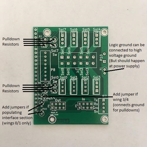
| + | ==== Solenoid Plank Assembly ==== | ||
| + | |||
| + | The parts for the ''Solenoid'' plank are the eight MOSFETs, eight 10K Resistors, a 2x6 header and a 8-pin locking header. | ||
| + | |||
| + | When assembling, start with the shortest components and work towards tallest - resistors and jumpers, headers, and lastly, MOSFETs. The 2x6 header should be installed with the locking tab facing "down" as in the silkscreen. | ||
| + | |||
| + | [[Image:solenoid-assembly.jpg]] | ||
| + | |||
| + | === STM32F103 === | ||
| + | |||
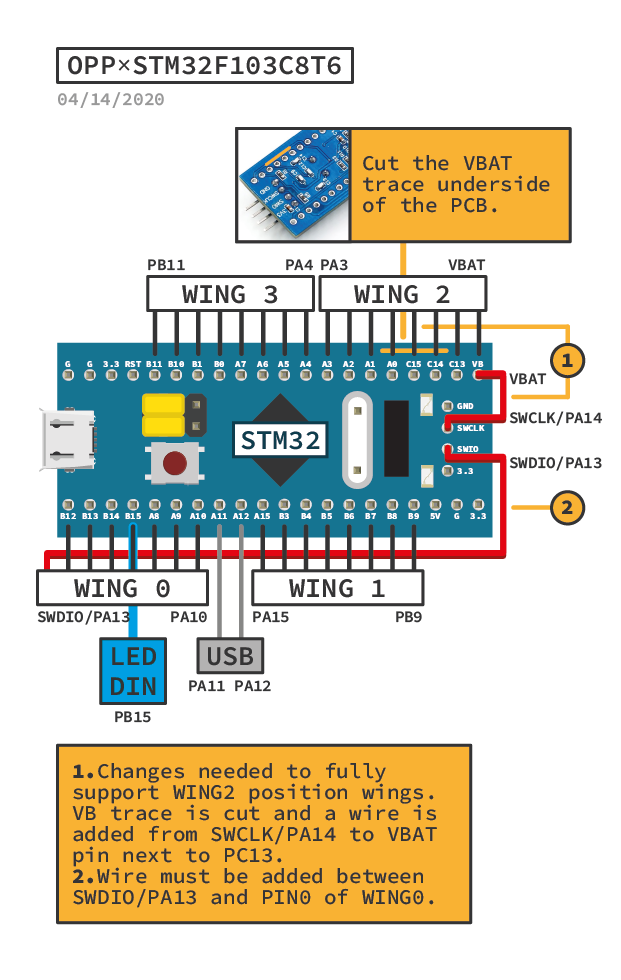
| + | [[File:STM32ChangesToSupportAllWings.png]] | ||
| + | |||
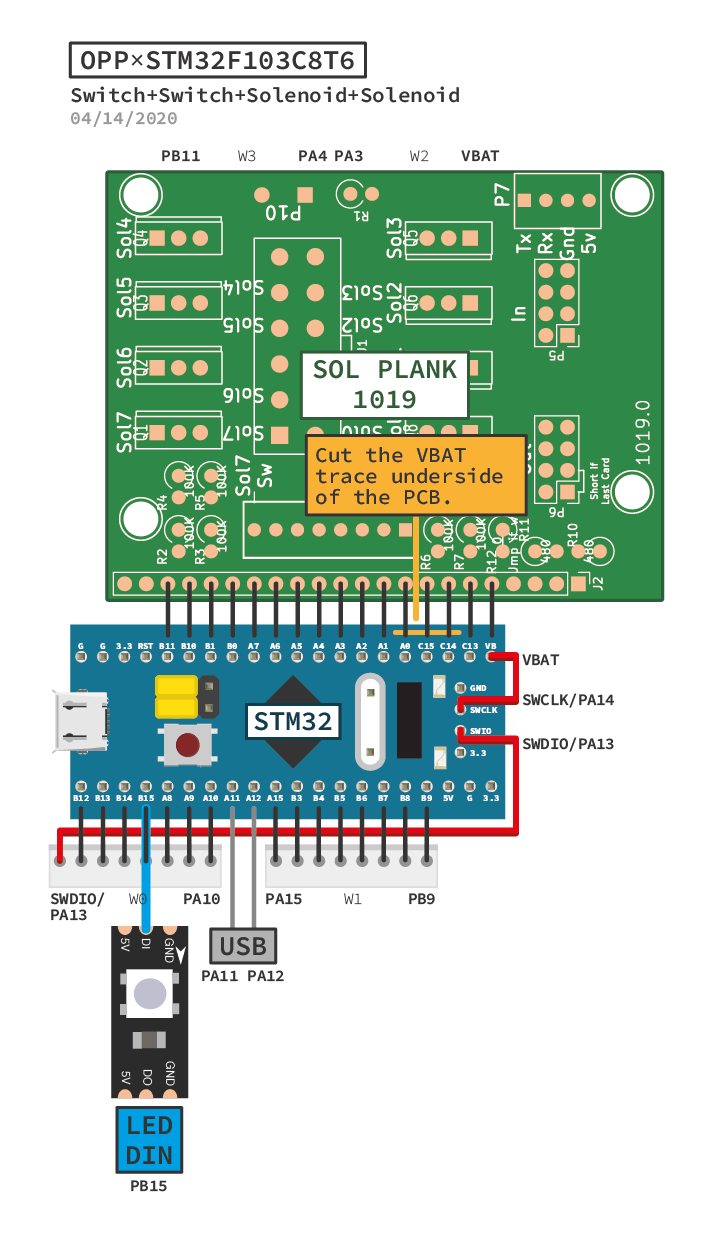
| + | [[File:STM32NeoInpPlank.png]] | ||
| + | |||
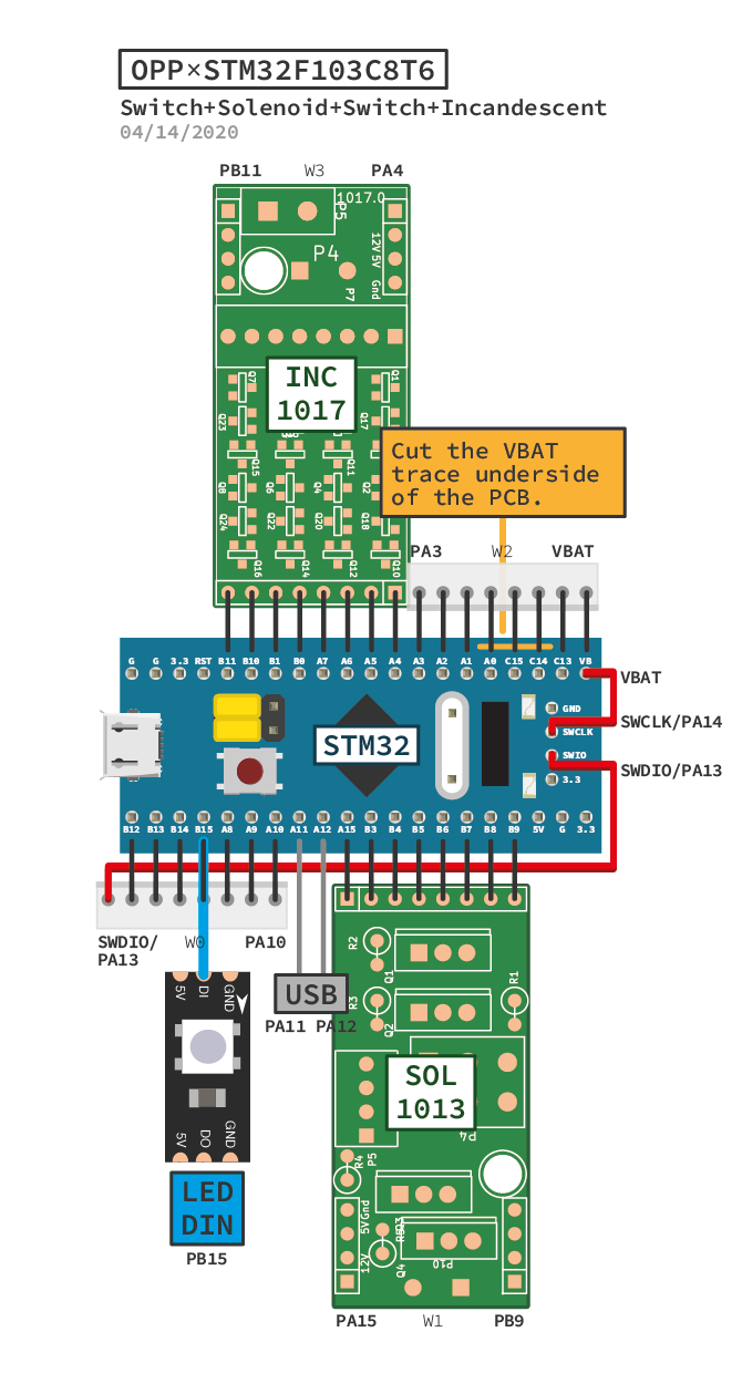
| + | [[File:STM32NeoSolInpIncand.png]] | ||
| + | |||
| + | === PSOC4200 === | ||
==== Processor Board Assembly ==== | ==== Processor Board Assembly ==== | ||
| Line 547: | Line 617: | ||
The final step is to connect VDD and GND to the ''Interface'' wing by soldering wire from the ''Processor'' board to the ''Interface'' wing as per the diagram - GND to '''Pin 1''' and 5V to '''Pin 2'''. This is required to power all the downstream ''Processor'' boards as none of them will be plugged into the USB connector which normally provides power. The 8-pin ribbon cable used for serial communications also provides 5V and ground connections. | The final step is to connect VDD and GND to the ''Interface'' wing by soldering wire from the ''Processor'' board to the ''Interface'' wing as per the diagram - GND to '''Pin 1''' and 5V to '''Pin 2'''. This is required to power all the downstream ''Processor'' boards as none of them will be plugged into the USB connector which normally provides power. The 8-pin ribbon cable used for serial communications also provides 5V and ground connections. | ||
| − | ==== | + | ==== Attaching solenoid wing to PSOC4200 ==== |
| − | |||
| − | |||
[[Image:solenoid-assembly.png]] | [[Image:solenoid-assembly.png]] | ||
| − | |||
| − | |||
After assembly, it can be soldered in the appropriate spot on the ''Processor'' board. It is recommended to place ''Solenoid'' boards in the '''Wing 0''' and '''Wing 1''' positions as this allows a short jumper to connect the logic (5V) ground wiring for the pulldown, as well as slightly better fitment due to the chip packaging on the ''Processor'' boards. However, it is not a requirement - ''Solenoid'' wings can be placed in any position, as long as the pulldown ground is properly wired. | After assembly, it can be soldered in the appropriate spot on the ''Processor'' board. It is recommended to place ''Solenoid'' boards in the '''Wing 0''' and '''Wing 1''' positions as this allows a short jumper to connect the logic (5V) ground wiring for the pulldown, as well as slightly better fitment due to the chip packaging on the ''Processor'' boards. However, it is not a requirement - ''Solenoid'' wings can be placed in any position, as long as the pulldown ground is properly wired. | ||
| Line 559: | Line 625: | ||
After soldering the ''Solenoid'' wing to the ''Processor'' board, use a solid wire jumper to tie it and the ''Interface'' board together on the very end through holes. This is a purely physical connection that helps add stability to the board - there is no electrical connection on those holes. A good source for a jumper wire are the leftover legs from the resistors after they've been soldered in and cut to length. | After soldering the ''Solenoid'' wing to the ''Processor'' board, use a solid wire jumper to tie it and the ''Interface'' board together on the very end through holes. This is a purely physical connection that helps add stability to the board - there is no electrical connection on those holes. A good source for a jumper wire are the leftover legs from the resistors after they've been soldered in and cut to length. | ||
| − | ==== | + | ==== Attaching incandescent wing to PSOC4200 ==== |
| − | |||
| − | |||
[[Image:incandescent-assembly.png]] | [[Image:incandescent-assembly.png]] | ||
| Line 567: | Line 631: | ||
'''NOTE:''' As the board was originally designed for BS170s, the screened artwork reflects the pinout for that part, but the pinout is reversed for the 2N7000, so it is critically important to install the MOSFETs in the '''REVERSED''' orientation from the artwork. | '''NOTE:''' As the board was originally designed for BS170s, the screened artwork reflects the pinout for that part, but the pinout is reversed for the 2N7000, so it is critically important to install the MOSFETs in the '''REVERSED''' orientation from the artwork. | ||
| − | The | + | Once assembly is complete and the wing is installed on the ''Processor'', a solid wire jumper should be installed on the end holes to provide stability. As with all wing boards other than the ''Interface'' board, the ''Incandescent'' wing can be installed in any of the four positions. |
| + | |||
| + | ==== Attaching switch wing to PSOC4200 ==== | ||
| + | |||
| + | [[Image:switch-assembly.png]] | ||
| + | |||
| + | ==== Attaching solenoid plank to PSOC4200 ==== | ||
| + | |||
| + | After assembly, it can be soldered in the appropriate spot on the ''Processor'' board. Be careful to line up the pins. If soldering as '''Interface''' , '''Wing 0''' and '''Wing 1''' positions, the bottom pin of the plank lines up with pin4.0 on the processor, and the top pin of the plank lines up with pin4.VDD. If soldering as '''Wing 2''' and '''Wing 3''' positions, the third pin from the bottom lines up with GND on the processor, and the top pin of the plank lines up with pin3.3SWDCLK. The bottom pin on the plank in this position should not be attached to VDD on USB to serial interface portion of the processor card. Make sure to add the extra jumper to attach the logic ground to the pulldown resistors when in '''Wing 2''' and '''Wing 3''' positions. | ||
| + | |||
| + | == Firmware == | ||
| + | |||
| + | The '''OPP''' boards aren't just about the physical hardware, there's also an operating system - to handle the serial communication with the host, moving messages along the serial chain, activating coils and lamp, and maintaining state for all the above. This software is known as '''Firmware''' and it runs on each ''Processor'' board. This is what talks to the host computer over USB. | ||
| + | |||
| + | The firmware is available for download via the [https://openpinballproject.wordpress.com/repository/ OPP SVN] repo. It must be copied to each ''Processor'' individually in order for them to work. If using a PSoC4200 a group of processors can be upgraded via the Serial Chain. The stm32f103c8t6 must currently be upgraded using the '''ST-LINK V2 JTAG debugger'''. | ||
| + | |||
| + | === stm32f103c8t6 === | ||
| + | |||
| + | The firmware must be copied onto the stm32f103 processor using a ST-LINK V2 JTAG debugger. (Don't worry, these only cost $1.50 or so) The JTAG debugger is used for programming if using Linux or Windows. | ||
| + | |||
| + | ===== Linux / MacOS Firmware Programming ===== | ||
| + | |||
| + | * Install libusb and git: <code>sudo apt-get install libusb-1.0-0-dev git</code> | ||
| + | * Move to home: <code>cd ~</code> | ||
| + | * Grab stlink code: <code>git clone https://github.com/texane/stlink</code> | ||
| + | * Move into stlink folder: <code>cd stlink</code> | ||
| + | * Build stlink: <code>make</code> | ||
| + | * Copy binary to /usr/bin: <code>sudo cp build/Release/bin/st-flash /usr/bin</code> | ||
| + | |||
| + | For MacOS, you can get the libraries from ''Homebrew'': | ||
| + | |||
| + | * libusb: https://formulae.brew.sh/formula/libusb | ||
| + | * stlink: https://formulae.brew.sh/formula/stlink | ||
| − | + | ===== Attaching the debugger and programming firmware ===== | |
| − | + | * Connect the four pins at the edge of the stm32f103c8t6 to 3.3V, SWD, SWCLK and GND to the pins on the ST-LINK V2 | |
| + | * Move the '''Boot0''' jumper from position '''0''' to '''1''' | ||
| + | * Plug the ST-LINK V2 into a USB port | ||
| + | * Program firmware (firmware is found at ''repos/Stm32Workbench/Gen3Images''): <code>sudo st-flash –format ihex write OppStm32.2.0.0.6.hex</code> | ||
| + | * After programming is completed (printing out Jolly Good!), unplug the ST-LINK V2 from the USB port | ||
| + | * Move the Boot0 jumper from position 1 to 0 | ||
| − | + | ===== Verify firmware version ===== | |
| − | + | * Plug the stm32f103c8t6 into a USB port | |
| + | * Run Gen2Test.py (Gen2Test is found at repos/Python/Gen2Test): <code>sudo python Gen2Test.py -port=/dev/ttyACM0</code> | ||
| − | + | Note: Gen2Test.py may need to be run a few times to “sync” the serial port because plugging in the USB port may send garbage on the serial port. | |
| − | + | ===== Windows Firmware Programming ===== | |
| − | + | Install required software: | |
| − | + | * Download STSW-LINK004 from http://www.st.com: https://www.st.com/en/development-tools/stsw-link004.html | |
| + | * Run setup.exe found in the zip file. This will install the STM32 ST-Link Utility | ||
| − | + | Attaching the debugger and programming firmware: | |
| − | + | * Connect the four pins at the edge of the stm32f103c8t6 to 3.3V, SWD, SWCLK and GND to the pins on the ST-LINK V2 | |
| + | * Move the Boot0 jumper from position 0 to 1 | ||
| + | * Plug the ST-LINK V2 into a USB port | ||
| + | * Run STM32 ST-Link Utility | ||
| + | ** File->Open File and browse and select firmware file (firmware is found at repos/Stm32Workbench/Gen3Images) | ||
| + | ** Target->Program and Verify | ||
| + | * After programming is completed, unplug the ST-LINK V2 from the USB port | ||
| + | * Move the Boot0 jumper from position 1 to 0 | ||
| − | + | Verify firmware version: | |
| − | = | + | * Plug the stm32f103c8t6 into a USB port |
| + | * Run Gen2Test.py (Gen2Test is found at repos/Python/Gen2Test): c:\Python27\python.exe Gen2Test.py -port=COM3 | ||
| − | + | Note: Gen2Test.py may need to be run a few times to “sync” the serial port because plugging in the USB port may send garbage on the serial port. | |
| − | + | === PSoC 4200 === | |
==== RX/TX Jumpers ==== | ==== RX/TX Jumpers ==== | ||
| Line 632: | Line 743: | ||
|} | |} | ||
| − | To determine the port, check the syslog on Mac/Linux or the ''System Console'' on | + | To determine the port, check the syslog on Mac/Linux or the ''System Console'' on Windows. |
Whatever the device name is, write it down as it will be needed for copying the firmware and all future communication with the ''Processor'' boards. | Whatever the device name is, write it down as it will be needed for copying the firmware and all future communication with the ''Processor'' boards. | ||
| Line 658: | Line 769: | ||
For Windows, download the [https://www.python.org/downloads/windows/ Latest Version] of Python 2.7 and follow the install instructions as listed. It should be in the <code>C:\Python27</code> directory (the default). | For Windows, download the [https://www.python.org/downloads/windows/ Latest Version] of Python 2.7 and follow the install instructions as listed. It should be in the <code>C:\Python27</code> directory (the default). | ||
| − | From the command line, change into the <code>opp/Python/cyflash/</code> directory. The ''cyflash'' utility can be | + | From the command line, change into the <code>opp/Python/cyflash/</code> directory. The ''cyflash'' utility can be invoked with the following parameters: |
'''Linux/Mac''' | '''Linux/Mac''' | ||
| Line 688: | Line 799: | ||
==== Gen2Test ==== | ==== Gen2Test ==== | ||
| − | '''Gen2Test''' is the '''OPP''' utility used to | + | '''Gen2Test''' is the '''OPP''' utility used to check ''Processor'' status, as well as '''erase''', '''load''' and '''save''' the ''Wing'' configuration prior to using it with the host controller. It uses an additional ''Python'' script as a config file that you define. Even if you use a framework like ''MPF'' that automatically sets up the ''Processor'' configs for you on startup, it is a good idea to configure each board and save the configs separately to prevent coil or lamp lock-on due to a wing being defined as a switch or other issues. |
==== Example Configuration Files ==== | ==== Example Configuration Files ==== | ||
| Line 953: | Line 1,064: | ||
At this point the controller boards are ready to be installed in the game and wired up to all solenoids, lamps and switches. | At this point the controller boards are ready to be installed in the game and wired up to all solenoids, lamps and switches. | ||
| + | |||
| + | '''Important Note''': When wiring up multiple power supplies for logic, coils and lamps/LEDs, it is ''critical'' to '''connect all grounds together at the power supplies''' to avoid a potential '''floating ground''' issue that can easily destroy your OPP boards. | ||
[[Image:connected-boards.jpg]] | [[Image:connected-boards.jpg]] | ||
| Line 982: | Line 1,095: | ||
Although designed specifically to be used with the Cyruss processors boards, the wings can be driven by alternative microcontrollers, such as ''Arduino'' and others. | Although designed specifically to be used with the Cyruss processors boards, the wings can be driven by alternative microcontrollers, such as ''Arduino'' and others. | ||
| − | === Connecting a Coil Wing to an Arduino === | + | ==== Connecting a Coil Wing to an Arduino ==== |
The +5V and +12V pins near R4 are unused for the basic operation of the MOSFETs. Only the ground pin near R4 is required. This should be connected to the ground coming from the +5V logic power source. It would also work to connect this directly to a ground pin on the ''Arduino''. If this pin is not grounded correctly or has an intermittent connection, you will see random MOSFET firing. | The +5V and +12V pins near R4 are unused for the basic operation of the MOSFETs. Only the ground pin near R4 is required. This should be connected to the ground coming from the +5V logic power source. It would also work to connect this directly to a ground pin on the ''Arduino''. If this pin is not grounded correctly or has an intermittent connection, you will see random MOSFET firing. | ||
| Line 990: | Line 1,103: | ||
The '''Auto Fire''' pin header is not used directly by the boards. It is simply a pass thru to pins 0 - 3. You can leave the 4 pin header off for most purposes. One possible use is to flip the header around and use it to make a more secure connection to the ground pin mentioned previously. | The '''Auto Fire''' pin header is not used directly by the boards. It is simply a pass thru to pins 0 - 3. You can leave the 4 pin header off for most purposes. One possible use is to flip the header around and use it to make a more secure connection to the ground pin mentioned previously. | ||
| − | === Driving Coils from the Arduino Software === | + | ==== Driving Coils from the Arduino Software ==== |
The ''Arduino'' '''digitalWrite''' command is quite slow, due to some error checking that is done in the background. This may introduce lag into the solenoid firing. A discussion of the problem, and how it can be remedied, can be found [http://www.instructables.com/id/Arduino-is-Slow-and-how-to-fix-it/ here]. | The ''Arduino'' '''digitalWrite''' command is quite slow, due to some error checking that is done in the background. This may introduce lag into the solenoid firing. A discussion of the problem, and how it can be remedied, can be found [http://www.instructables.com/id/Arduino-is-Slow-and-how-to-fix-it/ here]. | ||
| + | |||
| + | ==== Connecting a Coil Wing to MPF ==== | ||
| + | See the [http://docs.missionpinball.org/en/latest/hardware/opp/index.html MPF Documentation about OPP] for details. | ||
== Troubleshooting == | == Troubleshooting == | ||
Latest revision as of 22:47, 16 August 2022
Contents
Open Pinball Project
The Open Pinball Project (OPP) was started in 2012 as a resource for pinball makers to have an inexpensive, fully open sourced project for controlling custom pinball machines. It is currently on a second generation design and has had a successful Kickstarter run of boards and components currently in the hands of makers all over the world.
In 1Q 2020, it was decided to switch to a new layout, due to the unavailability of processor boards.
This page should be considered as a Work In Progress.
Archives on the previous layout can be found on Archives of OPP. More details on this change are available in the MPF Users forum.
Hardware
The OPP hardware is made up of three main components:
- The Processor board is a STM32F103C8 prototyping board that can be purchased from TODO.
- The Wing boards allow the control of solenoids, lamps, LEDs or input from switches.
- The Power Filter Board to allow the use of inexpensive switching power supplies.
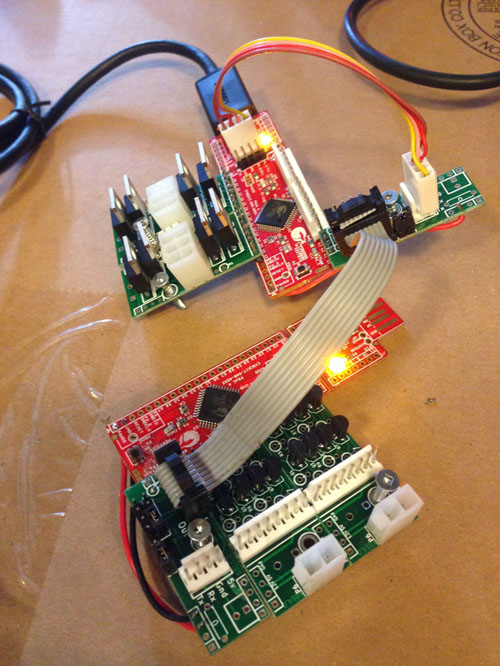
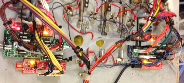
The following is an example of some fully assembled and wired OPP Processors with Wing boards.
Pictures to be added
Processor Boards
The Processor board can have up to four Wing boards controlling solenoids, incandescent lamps, or allowing input for switches. The Wing boards themselves can be combined in any configuration, so a single Processor board can support up to 16 solenoids (with 16 direct switch inputs), 32 switch inputs or 32 lamps. Each Wing board uses eight pins.
All other pins are unused.
Pictures to be added
The Processor itself does not run game rules or other game logic - a Controller like Mission Pinball running on a separate PC is still required to handle scoring and other game logic and to fire coils and light lamps as needed. The Processor simply provides the physical connection to playfield devices. However, coils can automatically be fired by the activation of their related direct switch input to allow a "white wood" mode that does not require a controller.
Solenoid Wing
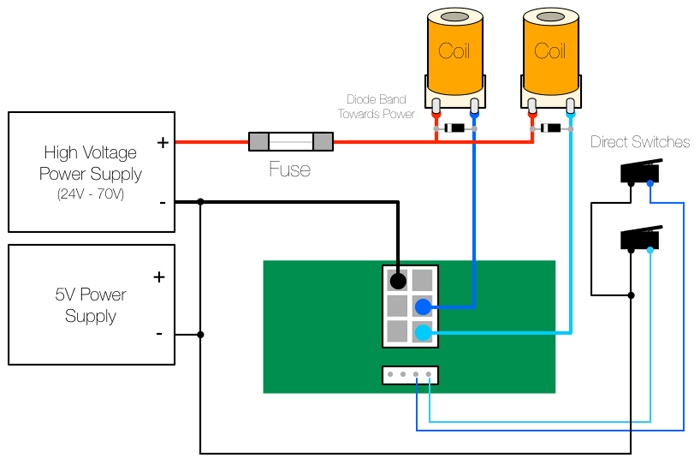
The Solenoid wing uses MOSFETs to control up to four individual coils via a ground sink method, where the coils themselves are wired to the positive side of the high voltage power supply and the MOSFET provides a ground path when activated, firing the coil.
Standard coil voltages are 24V to 48V and upwards of 10A of current.
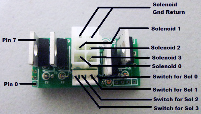
There are two connectors on the Solenoid wing - the larger 6-pin has four pins for the coil connections and two for ground. The 4-pin connector is for direct control switch inputs to control special solenoids.
Special Solenoids
For devices like flippers, slingshots or pop bumpers that require fast response to switch hits in order to fire coils, the Solenoid wing has four Direct Inputs that are used to directly activate the associated coil without the computer needing to detect a switch closure and send a solenoid activation command. These are known as Autofire coils. This direct activation can also be cancelled if needed by the Controller where theses switches can be considered as normal switches.
As of this writing, OPP only supports Autofire coils using the direct inputs or switch inputs on the same controller as the solenoid itself. This means you can't have an Autofire switch on another controller.
Another advantage to using the direct switches is that it allows the game to be tested without a host controller, since pop bumpers, slingshots and flippers will work at power-on.
The 4-pin connector for the direct switches can cause some packaging issues with the solenoid connector, so it is recommended to leave it out when building the boards if there is no need for Autofire coils.
Incandescent Wing
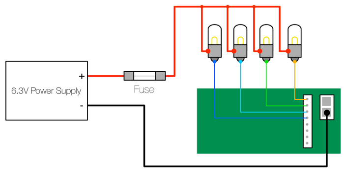
The Incandescent wing uses MOSFETs to control up to eight direct wired incandescent lamps via the same ground sink method as the coils.
Lamps require a high current 6.3V power supply as each bulb needs about .25A at full brightness.
Direct wired means that each lamp is wired up and controlled individually via the 8-pin connector, rather than in the Matrix style that most commercial pinball machines used until recently.
The other 2-pin connector is for the Ground connection.
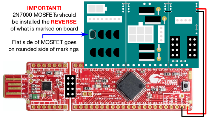
Note: This picture shows the MOSFETs reversed from the silkscreen which is required if using 2N7000TA MOSFETs which should be avoided. If using the BS-170 MOSFETs, the silkscreen matches the MOSFET orientation. Careful!
Switch Wing
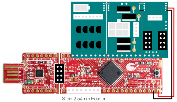
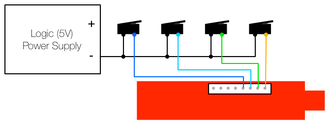
Switches are wired directly to the Processor board via an 8-pin 2.54mm locking header.
Picture to be added
Unlike the Solenoid and Incandescent wings, the Switch wing is set up as High-side, where the switch pins are at 5V and playfield and cabinet switches are tied to Ground, so that when a switch is activated, the pins are grounded and the switch is considered 'closed'. It is set up this way since the Processor pins have a Pull-Up resistor on them that is tied to 5V.
The switches provide a ground path for the normally-high inputs.
Power Filter Board
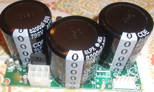
When firing solenoids, there is a large instantaneous draw of current from the power supply. A standard switching power supply may detect this as a short, and turn off. To prevent this from occurring, a large amount of bulk capacitance can be added, so the instantaneous current can be drawn from the bulk capacitors. Also, when initially charging the bulk capacitors, a large amount of current is drawn. A high power negative temperature coefficient (NTC) thermistor is used to reduce the initial current draw to charge the capacitors. This is the basis of the design for the Power Filter Board.
The board contains the following additional features:
- An LED to indicate when the capacitors are charged
- Ability to turn on/off the power by grounding a pin
- Output pin that can be used as an input to a processor for detecting if high voltage is enabled
- Board can be configured for one or two different high voltages through board population
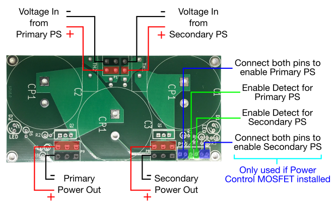
The power filter board can be configured to provide bulk capacitance for one or two power supplies. If two power supplies are needed, a second P-Channel MOSFET and inrush current limiter (NTC) must be bought.
If the ability to enable/disable the high power voltage isn't needed, a jumper can be added instead of the P-channel MOSFETs.
Before You Start
Prior to ordering and assembling the OPP boards, a number of tools and materials will need to be on hand, and a number of decisions will be made based on the pinball machine being built
Tools and Materials Required
To build and wire the OPP boards, you will need:
- Wire: Look on eBay for stranded wire in the 22-24AWG size.
- Side Cutters
- Pliers
- Soldering Iron: The Hakko FX888D is a popular, inexpensive brand. A lower-priced option is this iron from DX.
- Solder: Kester 44 is an excellent 63/37 solder. DX also has a less expensive option.
- Crimping Tool: Marco Specialities offers an inexpensive tool. Another option is the SN-28B ratcheting crimp tool - it can be purchased for less than $15 on eBay.
- Pin Extractor: Digikey has the Molex-branded tool for extracting the Mini-Fit Jr. style of square connectors used on the Solenoid wings.
Determine Board Layout
Prior to purchasing the OPP boards and components, you need to know how many solenoids, lamps and switches you need to support, where to put them, and how they will be mounted.
For example, a custom game might require 31 inputs, 10 solenoids (with 10 direct inputs), and 43 incandescent bulbs. This could be accomplished with four Processor boards and four Interface wings, three Solenoid wings, six Incandescent wings and five Switch wings. Technically this is more boards and wings than are strictly required, as the Processor boards could handle a denser wing configuration, but this layout cuts down on the total wiring required by placing Processors close to the devices they are controlling, saving significant time and materials.
Alternatively, consider a Williams Jokerz machine. It has 19 solenoids (including direct inputs), 39 switches and 63 incandescent bulbs (which includes 9 flashers). A possible layout for that is five Processor boards with five Interface wings, four Solenoid wings, eight Incandescent wings and five Switch wings.
You can place Processors near what is being controlled, or put them all together in the head of the machine like a traditional commercial pinball - it is entirely up to the maker as to where to place Processors, but placement will determine the final number of Processors and wings required.
Once the total number of Processor and Wing boards has been determined, and their approximate location in the final machine, parts can be ordered.
Power Supply Needs
When running solenoids and lamps, you'll need three voltages: 5V 3A for logic, 6.3V 10A for lamps and 24V to 48V 10A for solenoids (depending on what coils you use). See the Power Supply section for details of what is available.
An inexpensive option is to use a PC power supply, which provides high current 5V for logic and 12V for lamps. A high power DC-DC step down Buck Converter can be used to convert 12V to 6.3V for incandescents.
You can use a separate 24V to 48V 10A switcher for solenoids if you also use the Power Filter Board.
Getting Blank Boards
The OPP site itself does not sell blank boards and there currently is no one selling fully populated and tested boards. However, given the open source nature of the project, there are multiple ways to get the blanks.
The easiest is to order boards from MezelMods as they offer blanks for a very reasonable $1US per board.
The next option is to create Gerber files from the KiCad files located in the OPP SVN repository. For this you'll need to download KiCad, which is a printed circuit board design tool that was used to create the OPP boards. Once you have the Gerber files, they can be uploaded to a number of low-cost PCB manufacturers such as:
Each PCB maker has plusses and minuses that are too involved to go into in this wiki, but SeeedStudio has good prices and fast shipping.
Getting PCBs made can be a fairly advanced process, so it is recommended to simply purchase the already-made boards via MezelMods. They also offer additional parts that are less expensive than purchasing through Digikey or Mouser such as the FC-8P connectors and the 1x40 2.54 mm headers.
Getting Components
Once you have the bare boards, they will need to be fully populated with components, which are not included - they will need to be sourced separately. The following is a Bill of Materials (BoM) for each Processor and Wing board.
Processor Board
OPP has moved away from using PSOC4200 boards since they are no longer available. The firmware has been ported to use STM32F103C8T6 blue pill boards that are even cheaper. These boards can easily be purchased from either Ebay or Aliexpress. A programmer (ST Link-V2) is needed to program the firmware. Luckily, these are typically sold from the same vendors. In either Ebay or Aliexpress search for STM32F103C8T6. If using Aliexpress insure that the seller has sold at least a couple of hundred boards. Processor boards and the programmer are about $1.50 or $2.00 each plus shipping if willing to wait for shipping from China.
| Quantity | Mouser Part # | Description | Price Est. | Mezel Price |
|---|---|---|---|---|
| 1 | Ebay or Aliexpress | STM32F103C8T6 blue pill | $2.00/ea | N/A |
Note: The STM32F103C8T6 processor boards come with the headers so there is no need to purchase them anymore.
Solenoid Wing
| Quantity | Mouser Part # | Description | Price Est. |
|---|---|---|---|
| 4 | 942-IRL540NPBF | N-Channel MOSFET 100V 36A | $0.71/ea |
| 4 | 603-CFR-12JR-5210K | 10K Ohm Resistor (1/6W 5%) | $0.02/ea |
| 1 | 538-35317-0620 | Molex 6-pin 4.2 mm Mini-Fit Header | $0.28/ea |
| 6 | 538-39-00-0039 | Molex Crimp-Style 4.2 mm 24-18AWG Female Pins | $0.19/ea |
| 1 | 538-39-01-2065 | Molex 6-pin 4.2 mm Mini-Fit Housing | $0.52/ea |
| Parts Needed ONLY If Adding Direct Switches | |||
| 1 | 640454-4 | 4-pin Polarized 2.54 mm Header | $0.12/ea |
| 6 | 538-08-50-0136 | Molex Crimp-Style 2.54 mm KK Pins | $0.13/ea |
| 1 | 538-22-01-2047 | Molex 4-Pin 2.54 mm Housing | $0.17/ea |
Note: The total number of crimp-style pins included in the BoM is higher than actually needed to account for re-crimping.
Note 2: Since the price of the higher current (IRL540) MOSFETs have dropped, it now makes sense just to use these MOSFETs for all configurations.
Incandescent Wing
| Quantity | Mouser Part # | Description | Price Est. |
|---|---|---|---|
| 8 | 512-BS170 | N-Channel MOSFET 60V 500mA | $0.39/ea |
| 1 | 538-35317-0220 | Molex 2-pin 4.2 mm Header | $0.12/ea |
| 1 | 538-39-01-2025 | Molex 2-pin 4.2 mm Housing | $0.33/ea |
| 3 | 538-39-00-0039 | Molex Crimp-Style 4.2 mm 24-18AWG Female Pins | $0.19/ea |
| 1 | 571-6404548 | 8-pin 2.54 mm Polarized Header | $0.45/ea |
| 1 | 538-22-01-2087 | Molex 8-pin 2.54 mm Housing | $0.32/ea |
| 10 | 538-08-50-0136 | Molex Crimp-Style 2.54 mm KK Pins | $0.13/ea |
| Lower Current alternative MOSFET that should be avoided | |||
| 8 | 512-2N7000TA | MOSFET 60V N-Channel | $0.33/ea |
Switch Wing
| Quantity | Mouser Part # | Description | Price Est. |
|---|---|---|---|
| 1 | 571-6404548 | 8-pin 2.54 mm Polarized Header | $0.45/ea |
| 1 | 538-22-01-2087 | Molex 8-pin 2.54 mm Housing | $0.32/ea |
| 10 | 538-08-50-0136 | Molex Crimp-Style 2.54 mm KK Pins | $0.13/ea |
Note: The Switch wing is just the 8-pin headers soldered directly to the Processor board with the upright lock facing out from the board.
Interface Wing
Interface wing boards are no longer needed if using the newer STM32F103 processor boards. Each STM32F103 is connected to the host computer with a USB cable. This eliminates the need for the interface board.
| Quantity | Mouser Part # | Description | Price Est. | Mezel Price |
|---|---|---|---|---|
| 2 | 649-68602-108HLF | 2 x 4 position 2.54 mm Header | $0.45/ea | $0.20/ea |
| 1 | 640454-4 | Molex 4-Pin 2.54 mm Polarized Header | $0.12/ea | N/A |
| 2 | 538-22-01-2047 | Molex 4-Pin 2.54 mm Housing | $0.17/ea | N/A |
| 10 | 538-08-50-0136 | Molex Crimp-Style 2.54 mm KK Pins | $0.13/ea | N/A |
| 2 | eBay (search "FC-8P") | FC-8P IDC Socket 2.54 mm | ~ $0.10/ea | $0.20/ea |
| ~10ft | eBay (search "8 pin IDC cable") | 8-pin IDC Flat cable | ~$1/ft | N/A |
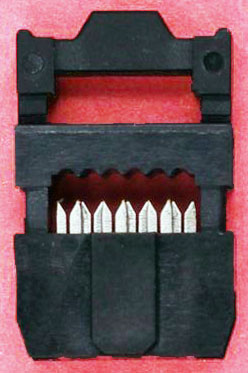
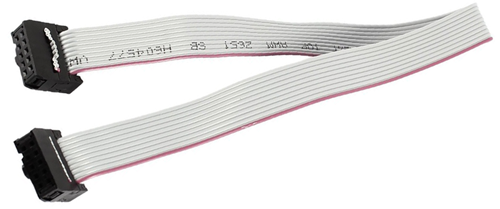
Note: Neither Mouser nor Digikey have FC-8P connectors or flat cable in stock, so eBay is the best source for these parts. Mezel Mods sells FC-8P connectors and 2x4 Pin headers for a lower price.
Power Filter Board
| Qty / 1 Switcher | Qty / 2 Switcher | Mouser Part # | Description | Price Est. |
|---|---|---|---|---|
| 1 | 1 | PCB | PCB from Mezel Mods | $5.00/ea |
| 3 | 3 | 598-SLPX822M063H5P3 | Bulk Capacitor, 8.2mF, 63V | $4.28/ea |
| 1 | 2 | 995-SG26 | Inrush current limiter (NTC Thermistor) | $2.28/ea |
| 2 | 3 | 538-35317-0620 | Molex 6-pin 4.2 mm Mini-Fit Header | $0.28/ea |
| 1 | 2 | 511-STF10P6F6 | P - Channel MOSFET | $0.85/ea |
| 3 | 6 | 588-OK1045E-R52 | 100K Ohm Resistor | $0.02/ea |
| 1 | 2 | 696-SLX-LX5093ID | High voltage 5mm (T-1 3/4) indicator LED | $0.06/ea |
| 12 | 18 | 538-39-00-0039 | Molex Crimp-Style 4.2 mm 24-18AWG Female Pins | $0.19/ea |
| 2 | 3 | 538-39-01-2065 | Molex 6-pin 4.2 mm Mini-Fit Housing | $0.52/ea |
| 1 | 1 | 571-6404566 | FRICTION LCK 6P Header | $0.38/ea |
The power filter board can be configured to provide bulk capacitance for one or two power supplies. If two power supplies are needed, a second P-Channel MOSFET and inrush current limiter must be bought.
If the ability to enable/disable the high power voltage isn't needed, a jumper can be added instead of the P-channel MOSFETs.
Note: Another through-hole resistor is needed if planning to allow a processor to read if the voltage is enabled or not. A simple voltage divider is used to convert the high voltage to the processor input voltage. The value of that resistor is different depending on the input voltage from your power supply and the input voltage of the processor. The table lists the 1% and 5% standard value resistor. (Choose the cheapest):
| Input Voltage | Processor Voltage | Resistor Ohm | 1% Resistor | 5% Resistor |
|---|---|---|---|---|
| 24V | 5V | 380K | 383K | 390K |
| 48V | 5V | 860K | 866K | 910K |
| 70V | 5V | 1.3M | 1.3M | 1.3M |
| 24V | 3.3V | 628K | 634K | 680K |
| 48V | 3.3V | 1.35M | 1.37M | 1.5M |
| 70V | 3.3V | 2.02M | 2.05M | 2.2M |
The equation to calculate the resistor value is:
(Power Supply Voltage * 100K) / Processor Voltage - 100K = Resistor
Solenoid Plank
| Quantity | Mouser Part # | Description | Price Est. |
|---|---|---|---|
| 8 | 942-IRL540NPBF | N-Channel MOSFET 100V 36A | $0.71/ea |
| 8 | 603-CFR-12JR-5210K | 10K Ohm Resistor (1/6W 5%) | $0.02/ea |
| 1 | 538-35317-1220 | Molex 12-pin 4.2 mm Mini-Fit Header | $0.66/ea |
| 12 | 538-39-00-0039 | Molex Crimp-Style 4.2 mm 24-18AWG Female Pins | $0.19/ea |
| 1 | 538-39-01-2125 | Molex 12-pin 4.2 mm Mini-Fit Housing | $0.74/ea |
| Parts Needed ONLY If Adding Direct Switches | |||
| 1 | 571-6404548 | 8-pin 2.54 mm Polarized Header | $0.45/ea |
| 12 | 538-08-50-0136 | Molex Crimp-Style 2.54 mm KK Pins | $0.13/ea |
| 1 | 538-22-01-2087 | Molex 8-pin 2.54 mm Housing | $0.32/ea |
Note: The total number of crimp-style pins included in the BoM is higher than actually needed to account for re-crimping. The interface section can only be populated if the plank board is installed as wing 0, wing 1 and using PSOC4200 processor boards.
Note 2: Since the price of the higher current (IRL540) MOSFETs have dropped, it now makes sense just to use these MOSFETs for all configurations.
Assembly
Once all the boards and the components are available, you can begin assembly.
Common
Solenoid Wing Assembly
The parts for the Solenoid wing are the four MOSFETs, four 10K Resistors, a 2x3 header and a 4-pin locking header. If you are not using the direct switch capabilities of the Solenoid wing, it is recommended to leave the 4-pin out of the build as it causes some packaging issues when placing wings next to each other, as the 2x3 header sticks off the end of the board slightly and makes contact with the 4-pin header on the adjacent wing.
Start with the smallest components and work upwards - resistors, MOSFETs then headers. The 2x3 header should be installed with the locking tab facing "up" as in the above diagram.
Incandescent Wing Assembly
The through-hole Incandescent wing parts are eight 2N7000 MOSFETs, an 1x8 locking header for lamp connections and a 2-pin header for the 12V ground connection. No resistors are required, so all resistor spots are left empty.
The tab for the 2-pin header should face inwards towards the center of the board.
Switch Wing Assembly
There is no physical wing board required for the Switch wing - it consists entirely of a single 8-pin 2.54mm locking header connected directly to the Processor board.
Power Filter Board
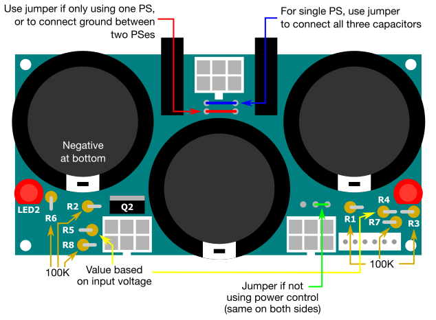
Install jumpers, resistors, LEDs, MOSFETs and connectors first, then thermistors and finally the three capacitors with the negative leg facing towards the bottom of the board. LEDs are installed with the flat part facing down.
If not using the power control capability of the board, the MOSFETs and their associated resistors are not needed.
Power Filter Board, One Voltage Supply, No Controls
The power filter board tries to be all things to all people. As such, it can be confusing to know how to populate the board. This section describes how to populate a power filter board for a single power supply, no processor control or feedback to detect if power supply is on, and no safety LED for indicating capacitors are charged.
Purchase the first four items (first column quantities) from this table Filter Board Parts. Install the three bulk capacitors, one NTC thermistor (install in left position), and two 6-pin Molex connectors (install in top and left positions). Using the clipped off leads from the NTC thermistor, add the red and blue jumpers as seen in the image above. Lastly, add the two light green jumpers that are marked by Q1 and Q2 on the silkscreen. (Only one is shown in the above image, while the second is shown as a MOSFET. In both positions, the jumper needs to go between the middle and right holes as shown in the image)
Solenoid Plank Assembly
The parts for the Solenoid plank are the eight MOSFETs, eight 10K Resistors, a 2x6 header and a 8-pin locking header.
When assembling, start with the shortest components and work towards tallest - resistors and jumpers, headers, and lastly, MOSFETs. The 2x6 header should be installed with the locking tab facing "down" as in the silkscreen.
STM32F103
PSOC4200
Processor Board Assembly
As delivered, the Cypress PSoC 4200 board needs to have two traces on the USB to Serial portion of the board cut - the TX and RX lines. Use an X-Acto knife to cut the thin traces on both sides of the board and use a Multimeter to test between the two through holes to confirm there is no connectivity. This is important to prevent crosstalk on the serial lines.
After the lines are cut, the headers (or lock connectors if being used for switches) can be soldered in, along with the 2x4 header between the USB-to-Serial interface and the main board.
Interface Wing Assembly
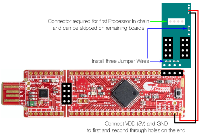
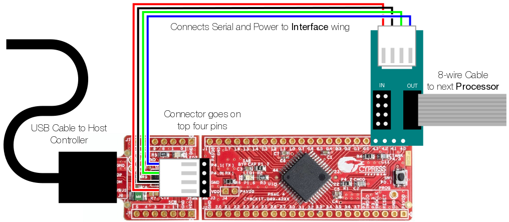
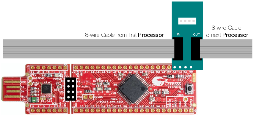
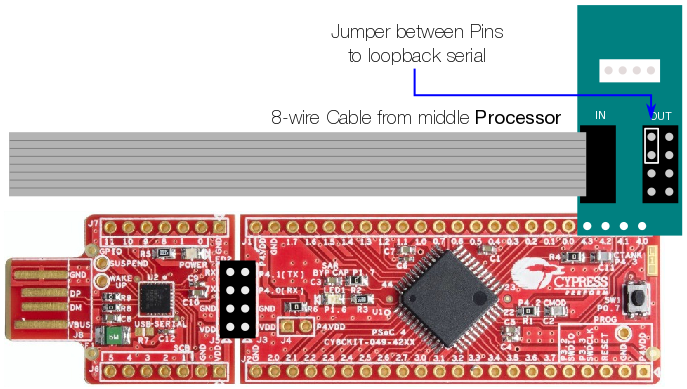
The main parts of the Interface wing are the two 2x4 headers for the serial connection and the 4-pin locking header that is used on the first Processor board to bring the Serial output from the USB-to-Serial card into the Interface wing. The 4-pin header is only required for the first Processor board in the chain, and can be left out when building the wing for subsequent boards.
It is best to start with the smallest components and work up - solder the two termination jumpers (marked as R2 and R3) and the serial connector enable jumper as depicted in the diagram, then the 2x4 headers, and finally the 4-pin header if needed.
Once assembled, the Interface board can be soldered to the Processor board on the last four pins marked 4.0 through 4.3 as per the diagram.
The final step is to connect VDD and GND to the Interface wing by soldering wire from the Processor board to the Interface wing as per the diagram - GND to Pin 1 and 5V to Pin 2. This is required to power all the downstream Processor boards as none of them will be plugged into the USB connector which normally provides power. The 8-pin ribbon cable used for serial communications also provides 5V and ground connections.
Attaching solenoid wing to PSOC4200
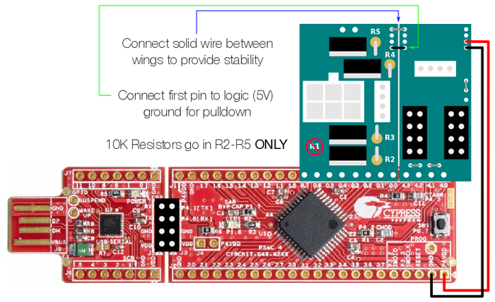
After assembly, it can be soldered in the appropriate spot on the Processor board. It is recommended to place Solenoid boards in the Wing 0 and Wing 1 positions as this allows a short jumper to connect the logic (5V) ground wiring for the pulldown, as well as slightly better fitment due to the chip packaging on the Processor boards. However, it is not a requirement - Solenoid wings can be placed in any position, as long as the pulldown ground is properly wired.
After soldering the Solenoid wing to the Processor board, use a solid wire jumper to tie it and the Interface board together on the very end through holes. This is a purely physical connection that helps add stability to the board - there is no electrical connection on those holes. A good source for a jumper wire are the leftover legs from the resistors after they've been soldered in and cut to length.
Attaching incandescent wing to PSOC4200
NOTE: As the board was originally designed for BS170s, the screened artwork reflects the pinout for that part, but the pinout is reversed for the 2N7000, so it is critically important to install the MOSFETs in the REVERSED orientation from the artwork.
Once assembly is complete and the wing is installed on the Processor, a solid wire jumper should be installed on the end holes to provide stability. As with all wing boards other than the Interface board, the Incandescent wing can be installed in any of the four positions.
Attaching switch wing to PSOC4200
Attaching solenoid plank to PSOC4200
After assembly, it can be soldered in the appropriate spot on the Processor board. Be careful to line up the pins. If soldering as Interface , Wing 0 and Wing 1 positions, the bottom pin of the plank lines up with pin4.0 on the processor, and the top pin of the plank lines up with pin4.VDD. If soldering as Wing 2 and Wing 3 positions, the third pin from the bottom lines up with GND on the processor, and the top pin of the plank lines up with pin3.3SWDCLK. The bottom pin on the plank in this position should not be attached to VDD on USB to serial interface portion of the processor card. Make sure to add the extra jumper to attach the logic ground to the pulldown resistors when in Wing 2 and Wing 3 positions.
Firmware
The OPP boards aren't just about the physical hardware, there's also an operating system - to handle the serial communication with the host, moving messages along the serial chain, activating coils and lamp, and maintaining state for all the above. This software is known as Firmware and it runs on each Processor board. This is what talks to the host computer over USB.
The firmware is available for download via the OPP SVN repo. It must be copied to each Processor individually in order for them to work. If using a PSoC4200 a group of processors can be upgraded via the Serial Chain. The stm32f103c8t6 must currently be upgraded using the ST-LINK V2 JTAG debugger.
stm32f103c8t6
The firmware must be copied onto the stm32f103 processor using a ST-LINK V2 JTAG debugger. (Don't worry, these only cost $1.50 or so) The JTAG debugger is used for programming if using Linux or Windows.
Linux / MacOS Firmware Programming
- Install libusb and git:
sudo apt-get install libusb-1.0-0-dev git - Move to home:
cd ~ - Grab stlink code:
git clone https://github.com/texane/stlink - Move into stlink folder:
cd stlink - Build stlink:
make - Copy binary to /usr/bin:
sudo cp build/Release/bin/st-flash /usr/bin
For MacOS, you can get the libraries from Homebrew:
Attaching the debugger and programming firmware
- Connect the four pins at the edge of the stm32f103c8t6 to 3.3V, SWD, SWCLK and GND to the pins on the ST-LINK V2
- Move the Boot0 jumper from position 0 to 1
- Plug the ST-LINK V2 into a USB port
- Program firmware (firmware is found at repos/Stm32Workbench/Gen3Images):
sudo st-flash –format ihex write OppStm32.2.0.0.6.hex - After programming is completed (printing out Jolly Good!), unplug the ST-LINK V2 from the USB port
- Move the Boot0 jumper from position 1 to 0
Verify firmware version
- Plug the stm32f103c8t6 into a USB port
- Run Gen2Test.py (Gen2Test is found at repos/Python/Gen2Test):
sudo python Gen2Test.py -port=/dev/ttyACM0
Note: Gen2Test.py may need to be run a few times to “sync” the serial port because plugging in the USB port may send garbage on the serial port.
Windows Firmware Programming
Install required software:
- Download STSW-LINK004 from http://www.st.com: https://www.st.com/en/development-tools/stsw-link004.html
- Run setup.exe found in the zip file. This will install the STM32 ST-Link Utility
Attaching the debugger and programming firmware:
- Connect the four pins at the edge of the stm32f103c8t6 to 3.3V, SWD, SWCLK and GND to the pins on the ST-LINK V2
- Move the Boot0 jumper from position 0 to 1
- Plug the ST-LINK V2 into a USB port
- Run STM32 ST-Link Utility
- File->Open File and browse and select firmware file (firmware is found at repos/Stm32Workbench/Gen3Images)
- Target->Program and Verify
- After programming is completed, unplug the ST-LINK V2 from the USB port
- Move the Boot0 jumper from position 1 to 0
Verify firmware version:
- Plug the stm32f103c8t6 into a USB port
- Run Gen2Test.py (Gen2Test is found at repos/Python/Gen2Test): c:\Python27\python.exe Gen2Test.py -port=COM3
Note: Gen2Test.py may need to be run a few times to “sync” the serial port because plugging in the USB port may send garbage on the serial port.
PSoC 4200
RX/TX Jumpers
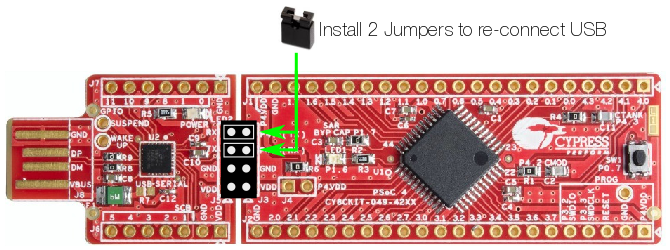
As part of the initial board setup, the RX/TX traces were cut on the Processor board. In order to copy the firmware to the board, jumpers will need to be put in place to connect the two serial pins on the USB-to-Serial interface to the board itself.
Determine your USB Device
In order to talk to the Processor via the host computer's USB port, a device driver will likely need to be installed. Cypress offers device drivers for Windows, Linux and Mac.
Install the appropriate driver for your host computer following the instructions from the Cypress site.
Once installed, plugging the Processor into a USB port on the host computer should result in a device being mounted on your system, with an associated serial device - a COM port on Windows or a tty or cu file in the /dev directory for Linux and Mac.
Some typical Serial devices are listed below. Please note that this is not a definitive list as the operating systems will assign Serial ports dynamically, so for example on Windows it might be COM8 or COM10, or on OSX it might be /dev/cu.usbmodem1421, and so on.
| OS | Device |
|---|---|
| Windows | COM9 |
| Linux | /dev/ttys1 |
| OSX | /dev/cu.usbmodem1411 |
| Raspbian (Raspberry Pi Linux) | /dev/ttyACM0 |
To determine the port, check the syslog on Mac/Linux or the System Console on Windows.
Whatever the device name is, write it down as it will be needed for copying the firmware and all future communication with the Processor boards.
Raspberry Pi Serial
Specific to the Raspberry Pi setup, the default driver for the Cypress controller in the OS sees it as a thermometer, so the driver needs to be disabled. This is done by editing the /etc/modprobe.d/raspi-blacklist.conf file and inserting the following:
blacklist cytherm
If the file doesn't exist, create it.
After saving the file and exiting, do chmod 600 /etc/modprobe.d/raspi-blacklist.conf and then reboot the RPi. The processor should then appear as a USB device using the default serial driver.
cyflash
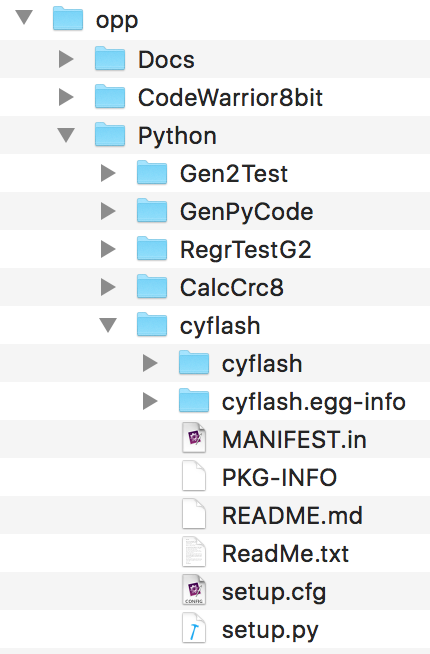
cyflash is a Python utility provided by Cypress to copy firmware to the board. It is included as part of the OPP SVN repo under the Python/cyflash directory.
The instructions for downloading the SVN repo are detailed on the main SVN page. Once downloaded to the local filesystem into a directory called opp, do a directory listing to confirm the cyflash files are in place.
How the firmware is uploaded depends on which OS you use - Windows, Linux or Mac. Linux and Mac are a bit simpler as they already have the correct version of Python installed by default.
For Windows, download the Latest Version of Python 2.7 and follow the install instructions as listed. It should be in the C:\Python27 directory (the default).
From the command line, change into the opp/Python/cyflash/ directory. The cyflash utility can be invoked with the following parameters:
Linux/Mac
python -m cyflash.__main__ --serial /dev/[serial-device] --serial_baudrate 115200 ../../Creator/Gen2Images/Gen2.rev0.2.0.0.cyacd
Windows
c:\Python27\Python.exe -m cyflash.__main__ --serial COM[serial-device] --serial_baudrate 115200 ..\..\Creator\Gen2Images\Gen2.rev0.2.0.0.cyacd
Before running the command, you must put the Processor into bootloader mode. Plug the board in while holding down the small button at the end of the board, which will cause the blue LED to flash rapidly.
Running cyflash should begin to upload the firmware to the board.
% python -m cyflash.__main__ --serial /dev/cu.usbmodem1411 --serial_baudrate 115200 ../../Creator/Gen2Images/Gen2.rev0.2.0.0.cyacd
CyFlash version: 1.07
Initialising bootloader.
Silicon ID 0x04c81193, revision 17.
Bootloader version: 1.20
Array 0: first row 32, last row 255.
Uploading data (128/128)
Device checksum verifies OK.
Rebooting device.
When it is complete, the board should reboot and the LED stop flashing. The board is now ready for configuring the Wing layout.
For versions of firmware greater than 0.2.0.1 it is possible to upgrade without having to disconnect each processor board and program separately. This is covered in the next section.
Gen2Test
Gen2Test is the OPP utility used to check Processor status, as well as erase, load and save the Wing configuration prior to using it with the host controller. It uses an additional Python script as a config file that you define. Even if you use a framework like MPF that automatically sets up the Processor configs for you on startup, it is a good idea to configure each board and save the configs separately to prevent coil or lamp lock-on due to a wing being defined as a switch or other issues.
Example Configuration Files
Here are some examples of wing config files. They are not included in the SVN repo, but can be copied and used for configuring boards if saved with a .py extension.
2sol2switch.py: This config sets Wing 0-1 to Solenoid wings, and Wing 2-3 to Switch wings.
testVers = '00.00.01'

import rs232Intf

# Config inputs as all state inputs
wingCfg = [ [ rs232Intf.WING_SOL, rs232Intf.WING_SOL, rs232Intf.WING_INP, rs232Intf.WING_INP ] ]

# Config inputs as all state inputs
inpCfg = [ [ rs232Intf.CFG_INP_STATE, rs232Intf.CFG_INP_STATE, rs232Intf.CFG_INP_STATE, rs232Intf.CFG_INP_STATE, \
             rs232Intf.CFG_INP_STATE, rs232Intf.CFG_INP_STATE, rs232Intf.CFG_INP_STATE, rs232Intf.CFG_INP_STATE, \
             rs232Intf.CFG_INP_STATE, rs232Intf.CFG_INP_STATE, rs232Intf.CFG_INP_STATE, rs232Intf.CFG_INP_STATE, \
             rs232Intf.CFG_INP_STATE, rs232Intf.CFG_INP_STATE, rs232Intf.CFG_INP_STATE, rs232Intf.CFG_INP_STATE, \
             rs232Intf.CFG_INP_STATE, rs232Intf.CFG_INP_STATE, rs232Intf.CFG_INP_STATE, rs232Intf.CFG_INP_STATE, \
             rs232Intf.CFG_INP_STATE, rs232Intf.CFG_INP_STATE, rs232Intf.CFG_INP_STATE, rs232Intf.CFG_INP_STATE, \
             rs232Intf.CFG_INP_STATE, rs232Intf.CFG_INP_STATE, rs232Intf.CFG_INP_STATE, rs232Intf.CFG_INP_STATE, \
             rs232Intf.CFG_INP_STATE, rs232Intf.CFG_INP_STATE, rs232Intf.CFG_INP_STATE, rs232Intf.CFG_INP_STATE ] ]

# solenoid config
solCfg  = [ [   rs232Intf.CFG_SOL_USE_SWITCH, '\x20', '\x00', rs232Intf.CFG_SOL_USE_SWITCH, '\x20', '\x00', \
                rs232Intf.CFG_SOL_USE_SWITCH, '\x20', '\x00', rs232Intf.CFG_SOL_USE_SWITCH, '\x20', '\x00', \
                rs232Intf.CFG_SOL_USE_SWITCH, '\x20', '\x00', rs232Intf.CFG_SOL_USE_SWITCH, '\x20', '\x00', \
                rs232Intf.CFG_SOL_USE_SWITCH, '\x20', '\x00', rs232Intf.CFG_SOL_USE_SWITCH, '\x20', '\x00', \
                '\x00', '\x00', '\x00', '\x00', '\x00', '\x00', \
                '\x00', '\x00', '\x00', '\x00', '\x00', '\x00', \
                '\x00', '\x00', '\x00', '\x00', '\x00', '\x00', \
                '\x00', '\x00', '\x00', '\x00', '\x00', '\x00' ] ]
4incand.py: This config sets all four wings to Incandescent.
testVers = '00.00.01'

import rs232Intf

# Config inputs as all state inputs
wingCfg = [ [ rs232Intf.WING_INCAND, rs232Intf.WING_INCAND, rs232Intf.WING_INCAND, rs232Intf.WING_INCAND ] ]

# Config inputs as all state inputs
inpCfg = [ [ rs232Intf.CFG_INP_STATE, rs232Intf.CFG_INP_STATE, rs232Intf.CFG_INP_STATE, rs232Intf.CFG_INP_STATE, \
             rs232Intf.CFG_INP_STATE, rs232Intf.CFG_INP_STATE, rs232Intf.CFG_INP_STATE, rs232Intf.CFG_INP_STATE, \
             rs232Intf.CFG_INP_STATE, rs232Intf.CFG_INP_STATE, rs232Intf.CFG_INP_STATE, rs232Intf.CFG_INP_STATE, \
             rs232Intf.CFG_INP_STATE, rs232Intf.CFG_INP_STATE, rs232Intf.CFG_INP_STATE, rs232Intf.CFG_INP_STATE, \
             rs232Intf.CFG_INP_STATE, rs232Intf.CFG_INP_STATE, rs232Intf.CFG_INP_STATE, rs232Intf.CFG_INP_STATE, \
             rs232Intf.CFG_INP_STATE, rs232Intf.CFG_INP_STATE, rs232Intf.CFG_INP_STATE, rs232Intf.CFG_INP_STATE, \
             rs232Intf.CFG_INP_STATE, rs232Intf.CFG_INP_STATE, rs232Intf.CFG_INP_STATE, rs232Intf.CFG_INP_STATE, \
             rs232Intf.CFG_INP_STATE, rs232Intf.CFG_INP_STATE, rs232Intf.CFG_INP_STATE, rs232Intf.CFG_INP_STATE ] ]

# solenoid config
solCfg  = [ [   '\x00', '\x00', '\x00', '\x00', '\x00', '\x00', \
                '\x00', '\x00', '\x00', '\x00', '\x00', '\x00', \
                '\x00', '\x00', '\x00', '\x00', '\x00', '\x00', \
                '\x00', '\x00', '\x00', '\x00', '\x00', '\x00', \
                '\x00', '\x00', '\x00', '\x00', '\x00', '\x00', \
                '\x00', '\x00', '\x00', '\x00', '\x00', '\x00', \
                '\x00', '\x00', '\x00', '\x00', '\x00', '\x00', \
                '\x00', '\x00', '\x00', '\x00', '\x00', '\x00' ] ]
2incand2switch.py: This config sets Wing 0-1 as Incandescent and Wing 2-3 as Switch.
testVers = '00.00.01'

import rs232Intf

# Config inputs as all state inputs
wingCfg = [ [ rs232Intf.WING_INCAND, rs232Intf.WING_INCAND, rs232Intf.WING_INP, rs232Intf.WING_INP ] ]

# Config inputs as all state inputs
inpCfg = [ [ rs232Intf.CFG_INP_STATE, rs232Intf.CFG_INP_STATE, rs232Intf.CFG_INP_STATE, rs232Intf.CFG_INP_STATE, \
             rs232Intf.CFG_INP_STATE, rs232Intf.CFG_INP_STATE, rs232Intf.CFG_INP_STATE, rs232Intf.CFG_INP_STATE, \
             rs232Intf.CFG_INP_STATE, rs232Intf.CFG_INP_STATE, rs232Intf.CFG_INP_STATE, rs232Intf.CFG_INP_STATE, \
             rs232Intf.CFG_INP_STATE, rs232Intf.CFG_INP_STATE, rs232Intf.CFG_INP_STATE, rs232Intf.CFG_INP_STATE, \
             rs232Intf.CFG_INP_STATE, rs232Intf.CFG_INP_STATE, rs232Intf.CFG_INP_STATE, rs232Intf.CFG_INP_STATE, \
             rs232Intf.CFG_INP_STATE, rs232Intf.CFG_INP_STATE, rs232Intf.CFG_INP_STATE, rs232Intf.CFG_INP_STATE, \
             rs232Intf.CFG_INP_STATE, rs232Intf.CFG_INP_STATE, rs232Intf.CFG_INP_STATE, rs232Intf.CFG_INP_STATE, \
             rs232Intf.CFG_INP_STATE, rs232Intf.CFG_INP_STATE, rs232Intf.CFG_INP_STATE, rs232Intf.CFG_INP_STATE ] ]

# solenoid config
solCfg  = [ [   '\x00', '\x00', '\x00', '\x00', '\x00', '\x00', \
                '\x00', '\x00', '\x00', '\x00', '\x00', '\x00', \
                '\x00', '\x00', '\x00', '\x00', '\x00', '\x00', \
                '\x00', '\x00', '\x00', '\x00', '\x00', '\x00', \
                '\x00', '\x00', '\x00', '\x00', '\x00', '\x00', \
                '\x00', '\x00', '\x00', '\x00', '\x00', '\x00', \
                '\x00', '\x00', '\x00', '\x00', '\x00', '\x00', \
                '\x00', '\x00', '\x00', '\x00', '\x00', '\x00' ] ]
The key lines in each file are wingCfg, which defines the layout, and solCfg, which sets the default values for each solenoid if a Solenoid wing is used on the Processor. InpCfg and the rest of the file are the same for each config.
wingCfg lists each wing type in order of wing position from 0 to 3. solCfg has three parameters per coil - the type of solenoid (USE_SWITCH, AUTO_CLR, ON_OFF_SOL, or DLY_KICK_SOL), initial kick time in milliseconds ("\x20" equals 32ms), and the last is the PWM duty cycle. "\x00" disables PWM. All values are in hexadecimal notation.
For a detailed explanation of what each value means, you can reference the documentation for the serial protocol (opp/Docs/brdIntf.pdf) in the SVN repo, as well as see the definitions for each value in the opp/Python/Gen2Test/rs232Intf.py script.
However, any of the above examples, or the included mdCfg file, will work as-is without needing a deep understanding of the firmware internals.
Check Processor Configurations
From the command line, change into the opp/Python/Gen2Test directory.
Plug in the Processor with the USB jumpers installed and run the command (with either C:\Python27\Python.exe or just python depending on your system):
Gen2Test.py -port=[serial-device]
Where the serial-device is the appropriate serial port on the host computer saved from earlier. The command should provide an inventory of the Wings as set by the firmware when it was uploaded. The default is all wings set to Switch.
% python Gen2Test.py -port=/dev/cu.usbmodem1411
Sending inventory cmd
Found 1 Gen2 brds.
Addr = ['0x20']
0x20 WingCfg = 0x02020202
0x20 INP_WING  INP_WING  INP_WING  INP_WING
If there are additional processors in the chain, it will display the configuration for all attached processors.
Erase Wing Configuration
To erase the existing config, run the command with the eraseCfg option:
% python Gen2Test.py -port=/dev/cu.usbmodem1411 -eraseCfg
Sending inventory cmd
Found 1 Gen2 brds.
Addr = ['0x20']
0x20 WingCfg = 0x02020202
0x20 INP_WING  INP_WING  INP_WING  INP_WING
Sent erase cfg command.
Save Wing Configuration
To save a new config, run the command with the saveCfg option and specify the config file with the loadCfg command.
% python Gen2Test.py -port=/dev/cu.usbmodem1411 -saveCfg -loadCfg=2sol2switch.py
Sending inventory cmd
Found 1 Gen2 brds.
Addr = ['0x20']
0x20 WingCfg = 0x02020202
0x20 INP_WING  INP_WING  INP_WING  INP_WING
loadFileName = 2sol2switch
Sending wing cfg.
Sending input cfg.
Sending solenoid cfg.
Skipping sending color table.
Sending save cfg command.
Done save cfg command.
Run Gen2Test again with just the port parameter to check the new configuration.
% python Gen2Test.py -port=/dev/cu.usbmodem1411
Sending inventory cmd
Found 1 Gen2 brds.
Addr = ['0x20']
0x20 WingCfg = 0x01010202
0x20 SOL_WING  SOL_WING  INP_WING  INP_WING
This configuration will persist between power cycles, so once this step is complete, Gen2Test will not be needed again except to test the connection between the host computer and the OPP boards. To perform that test, unplug and plug-in the Processor and run Gen2Test again to confirm the configuration is saved as above.
Upgrade Firmware
If you are at firmware revision 0.2.0.1 or higher, the following command should work to upgrade a whole chain of processors:
python Gen2Test.py -port=/dev/cu.usbmodem1411 -upgrade
It checks to see if all the cards have firmware version 0.2.0.1 or higher. At that point, it goes to the OPP/Creator/Gen2Images folder and looks for the newest version in that directory. Note that the files must end with the .cvacd extension.
It then upgrades each of the cards in turn, starting with the first card, ending with the last card in the chain. This process replaces the cumbersome single processor method for lower firmware revisions.
Display Switch Inputs
To debug switch inputs, you can run Gen2Test with the following command:
python Gen2Test.py -port=/dev/cu.usbmodem1411 -test=1 -card=0
The test=1 command reads the inputs from the card, and displays them on the screen as a single continuously updated line.
card=0 tells the test to display the inputs for the first card in the chain. This even works with switch matrices, so it gives you the direct inputs and the 64 switch matrix inputs. It can only do a single card at a time because it continuously overwrites the line.
Connecting Multiple Boards
Once each individual board is configured, the next step is to create the serial connection between boards by chaining them together via multiple 8-wire ribbon cables.
Serial Cables
The serial cables consist of standard 8-wire ribbon cable - usually a light grey or sometimes in rainbow colors - with FC-8P connectors on each end. These are IDC connectors, which is an acronym for Insulation Displacement Contact. IDC connectors displace the insulation on a wire to make a connection.
You place the wire flat inside the connector and compress the cover (using pliers or similar) to cut into the insulation and connect the wires. The cover locks and all 8 pins should now be connected. The ends can be trimmed with a side cutter or X-Acto knife. The connector should include a cap, used for extra support for the cable, under which the wire is bent prior to crimping.
Each FC-8P connector will have a positioning tab on the housing, and it is recommended to have the tab facing down towards the cable on one end and facing out on the other, so the tab is the same direction at the top and bottom. It isn't critical but it makes it easier to install cables knowing the tab always faces the same direction.
The finished cable should look similar to this example.
First Processor
The first board in the chain connects to the host controller via USB, and uses the integrated USB-to-Serial interface to connect to the Interface board via a 4-wire cable that must be constructed. This cable consists of two Molex 2.54mm housings and pins, which are part of the BoM for the Interface wing.
It connects 5V and Ground to power the other boards in the chain, as well as the TX and RX serial lines used for communicating between Processors.
If you are not familiar with crimping Molex connectors, you can read a detailed tutorial on the PinRepair site that covers proper connection crimping prior to constructing the cable.
Once both the 4-wire and ribbon cables are done, they can be connected to the Processor per the following diagram:
The Interface wing has two 2 x 4 2.54mm connectors labelled IN and OUT. The ribbon cable is connected to the OUT with the ribbon running down from the wing.
Middle Processor
The ribbon cable from the first board connects to the IN connector on the Interface wing of the middle Processor with the ribbon facing up, and another ribbon cable is connected to the OUT connector to lead to the next Processor. This is repeated for each additional Processor in the chain until the last one, so you will need multiple ribbon cables.
Last Processor
On the last Processor in the Serial Chain, the ribbon cable from the previous Processor is attached to the IN connector and a Jumper is placed between Pins 3-4 on the OUT connector, or the top right two pins, to terminate the chain by looping the serial connection together.
Without the jumper, the serial connection chain will not work and any commands will fail.
Testing the Chain
With the first Processor plugged into USB, all Processors should light up if wired correctly. If not, check the ribbon cables for correct orientation. Plugging them in backwards will not damage the boards but it will prevent them from getting power.
Note on this example of a two board chain, the yellow LEDs are lit on both boards, indicating a successful connection:
Running Gen2Test with only the port parameter should generate an inventory of all cards:
% python Gen2Test.py -port=/dev/cu.usbmodem1411
Sending inventory cmd
Found 2 Gen2 brds.
Addr = ['0x20', '0x21']
0x20 WingCfg = 0x01010202
0x20 SOL_WING  SOL_WING  INP_WING  INP_WING
0x21 WingCfg = 0x02020202
0x21 INP_WING  INP_WING  INP_WING  INP_WING
Wiring Examples
At this point the controller boards are ready to be installed in the game and wired up to all solenoids, lamps and switches.
Important Note: When wiring up multiple power supplies for logic, coils and lamps/LEDs, it is critical to connect all grounds together at the power supplies to avoid a potential floating ground issue that can easily destroy your OPP boards.
Solenoids
Solenoids are wired with positive voltage from the high voltage power supply (24V to 70V depending on your game) and the other lug to the Solenoid wing via the 2x6 Molex connector. When the MOSFET is triggered, it connects ground for that solenoid and it activates.
NOTE: a 4004 or similar diode must be placed across the positive and ground connections with the band towards the positive wire. This allows for the flyback voltage that is generated when a coil's magnetic field collapses. Without it, that voltage travels back to the Solenoid wing and will likely destroy the MOSFETs, so it is critical that the diode be in place.
Direct switches are connected via the 1x4 Molex connector and wired to the Logic (5V) ground.
Incandescent Lamps
Lamps are wired with positive voltage from the 6.3V power supply and connected to an Incandescent wing via the 1x8 Molex connector. The ground for the lamps is provided by the 1x2 Molex connector, which should be connected to the 6.3V power supply ground.
Switches
Switches are wired with ground from the logic (5V) power supply and connected to the Switch wing (directly to the Processor) via the 1x8 Molex connector. Power is provided via the Interface card from the USB connection.
Arduino and OPP
Although designed specifically to be used with the Cyruss processors boards, the wings can be driven by alternative microcontrollers, such as Arduino and others.
Connecting a Coil Wing to an Arduino
The +5V and +12V pins near R4 are unused for the basic operation of the MOSFETs. Only the ground pin near R4 is required. This should be connected to the ground coming from the +5V logic power source. It would also work to connect this directly to a ground pin on the Arduino. If this pin is not grounded correctly or has an intermittent connection, you will see random MOSFET firing.
Connect pins 4 - 7 to an Arduino pin configured for output and drive them high (+5V with the standard MOSFETs) to activate a solenoid.
The Auto Fire pin header is not used directly by the boards. It is simply a pass thru to pins 0 - 3. You can leave the 4 pin header off for most purposes. One possible use is to flip the header around and use it to make a more secure connection to the ground pin mentioned previously.
Driving Coils from the Arduino Software
The Arduino digitalWrite command is quite slow, due to some error checking that is done in the background. This may introduce lag into the solenoid firing. A discussion of the problem, and how it can be remedied, can be found here.
Connecting a Coil Wing to MPF
See the MPF Documentation about OPP for details.
Troubleshooting
If after assembling the boards and testing the connections they do not work, see below for some suggestions on next steps.
Python Errors
IndexError: string index out of range
This error means that the serial communication failed and no results were returned.
- Has the firmware been installed?
- Has the Processor been correctly configured for the wings that are installed?
- Is the yellow power LED on when plugged into USB?
- Are you using the correct serial port? Note that on Raspberry Pi PCs that the default driver for the Cypress processors needs to be disabled in
/etc/modprobe.d. See the Firmware section for details.
If the answers to the above questions are Yes, then the issue may be hardware related.
ImportError: No module named serial
This error is generated when you do not have the pyserial module installed on your host PC. It can be installed via pip install pyserial.
Download page for pyserial for Windows and other OSes: https://pypi.python.org/pypi/pyserial
Hardware Checklist
More often than not, due to having to self-assemble the boards, assembly errors can cause issues. Here is a checklist of possible reasons why a Processor may not respond to commands.
- Check 5V at multiple points: Interface wing, USB-to-Serial interface, bottom of Cypress board
- Check ground connections are correct and solid with no breaks in the solder
- Use a multimeter to confirm RX/TX lines are cut
- When testing a single board, confirm both RX and TX lines are correctly jumpered on USB-to-Serial interface
- When testing multiple boards, confirm all cables are correctly oriented
- When testing multiple boards, confirm last board is correctly terminated with a jumper on pins 3-4 of OUT connector
Contact OPP Support
If a reason for the failure cannot be found, the maintainer of the Open Pinball Project offers support via email at:
The maintainer is extremely responsive to questions and can often help find the issue with your setup. However, remember that OPP is run by volunteers, so they may not respond immediately to requests for help.

