Difference between revisions of "Construction"
(→Wire Management) |
(→Materials) |
||
| (116 intermediate revisions by 5 users not shown) | |||
| Line 3: | Line 3: | ||
=== Specialty Tools === | === Specialty Tools === | ||
| − | + | * '''[http://www.pinbits.com/index.php?main_page=product_info&products_id=59 Pop Bumper Drilling Template]''': For use when drilling the playfield for ''Williams''-style pop bumpers. Instructions for use [http://www.iobium.com/pop_bumper_drilling_template.htm here]. *[https://pinside.com/pinball/forum/topic/pinbits-appears-to-be-unresponsive#post-6768809 pinbits] appears to be out of business | |
| − | * | + | * '''Dupont KF2510 Crimper''': Usually priced under $20 on ebay, this connector crimper works incredibly well. Used with 100 mil spaced connectors, standard pinball molex connectors, and spade terminals. It has three different sizes for different connectors. The trick is to start the crimp so that the ratchet holds the connector in its teeth. Slip the wire in to the terminal, and then finish crushing the crimp. The crimps are nice and tight and hold the wires very securely. |
| + | |||
| + | * Amazon has [http://pinball-mods.com/url/tubularRivet tubular Riveting] tools and supplies from Hanson Rivet Supply. These rivets are typically used to attach plastics to metals in pinball machines. Example: Ramp flaps to Ramps. Lamp Sockets to Plastics. [https://pinside.com/pinball/forum/topic/river-die-size-and-rivets-for-ramps more detail] | ||
=== Metalworking Tools === | === Metalworking Tools === | ||
| Line 31: | Line 33: | ||
The above example is available from [http://www.harborfreight.com/36-inch-metal-brake-with-stand-91012.html Harbor Freight]. | The above example is available from [http://www.harborfreight.com/36-inch-metal-brake-with-stand-91012.html Harbor Freight]. | ||
| − | If space is at a premium, there are smaller [http://www.micromark.com/ | + | [[Image:tabletop-brake.jpg]] |
| + | |||
| + | If space is at a premium, there are smaller [http://www.micromark.com/Mini-Metal-Shear-and-Brake,12375.html tabletop] versions as well. | ||
[[Image:home-brake.jpg]] | [[Image:home-brake.jpg]] | ||
| Line 66: | Line 70: | ||
It is a bit that creates a locking edge between cabinet corners. | It is a bit that creates a locking edge between cabinet corners. | ||
| + | |||
| + | === Rotisserie === | ||
| + | While not a necessity, it makes populating a playfield much easier (both top and the bottom wiring and mechanics). This is true both of shopping an existing pin, and creating one from scratch. It's purpose is to hold the playfield securely, but still allowing it to be rotated 360 degrees (to flip back and forth between top and bottom surface). It also makes touching up playfield art easier and can prevent back pain by not having to crouch over a pinball cabinet. | ||
| + | |||
| + | It is also possible to test play a layout while mounted to a rotisserie, so long as it has been leveled and there are rails around the perimeter to keep the ball from falling off. Sometimes the cabinet walls are used as walls for the playfield. Flipper buttons will also need to be temporarily wired up to actuate the flippers, and a bracket to mount a plunger if testing skill shots. | ||
| + | |||
| + | Factories will often fabricate elaborate and sturdy rotisseries out of thick steel since they may be used thousands of times per year: | ||
| + | |||
| + | [[Image: Rotisserie production.jpeg|500px]] | ||
| + | |||
| + | A hobbyist rotisserie doesn't need to be this elaborate. The most common rotisserie plan available online uses black gas pipes as the base, an angle plate for the playfield to rest on, and C-clamps to keep the playfield mounted: | ||
| + | |||
| + | [[Image: Rotisserie_pipes.jpg|500px]] | ||
| + | |||
| + | This design is functional but not without flaws. It costs upwards of $50 in supplies, the clamps most use can mark the playfield if not careful, and it can sometimes be difficult to get it set up. An alternate is to build it out of wood (reducing the chances of scratching the playfield when mounted), and using toggle clamps with rubber tips to protect the playfield: | ||
| + | |||
| + | [[Image: Rotisserie_wooden.jpg|500px]] | ||
=== Advanced Tools === | === Advanced Tools === | ||
| Line 104: | Line 125: | ||
=== Plywood === | === Plywood === | ||
| − | Commercial pinball machines use a specially sourced | + | Commercial pinball machines use a specially sourced plywood that is not available from big box stores and generally not even specialty wood suppliers. Baltic Birch plywood has many more plys than big box store plywood. All the layers are Birch, so it is a very hard, heavy plywood. |
| + | |||
| + | [[Image:Birch_plywood.jpg|500px]] | ||
| + | |||
| + | The type of [http://www.menards.com/main/building-materials/panel-products/specialty-panels/hardwood-plywood/1-2-x-4-x-8-baltic-birch-plywood/p-1479673-c-13334.htm plywood] available at a big box store will have a thin ply on both sides, generally of softer '''Baltic Birch''', and will not have the surface area to allow a full 1/32" sanding to level the surface and inserts together. It will also have large voids inside. | ||
| − | + | [[Image: Plywood_box_store.jpg|500px]] | |
| − | + | The thickness of a raw playfield is '''17/32"''', which is then sanded on top with inserts installed to a finished size of '''1/2"'''. Each side is a full face of hard '''Birch''' with five plys in-between, not a thin veneer to allow for this sanding. The following photo illustrates the full seven plys: | |
| − | + | [[Image:plywood.png|500px]] | |
| − | For hobbyists, the best option is '''Cabinet Grade''' plywood, preferably from a lumber yard, with a minimum of seven plys but a preference for nine - the more plys, the more stable and flat. This type of plywood will have a thicker top and bottom ply suitable for sanding. It will generally be the softer | + | For hobbyists, the best option is '''Cabinet Grade''' plywood, preferably from a lumber yard, with a minimum of seven plys but a preference for nine - the more plys, the more stable and flat. This type of plywood will have a thicker top and bottom ply suitable for sanding. It will generally be the softer maple but for one-off games, it should prove acceptable. |
| − | [[Image:cabinet-grade.png]] | + | [[Image:cabinet-grade.png|500px]] |
| − | Another affordable option for whitewoods is '''Medium Density Fibreboard'''. Typically sold as '''MDF''', it is also available in large quantities. The drawback for MDF is that it has poor flexibility and does not allow for easy removal and re-installation of screwed in parts. | + | Another affordable option for whitewoods is '''Medium Density Fibreboard'''. Typically sold as '''MDF''', it is also available in large quantities. The drawback for MDF is that it has poor flexibility and does not allow for easy removal and re-installation of screwed in parts. It is also a very heavy material since it is so dense. It is highly recommended to avoid using MDF for final playfields. |
=== Sheetmetal === | === Sheetmetal === | ||
| Line 155: | Line 180: | ||
Once a preliminary [[Design|design]] is complete, the next step is to create an initial prototype, known in the industry as a '''Whitewood'''. | Once a preliminary [[Design|design]] is complete, the next step is to create an initial prototype, known in the industry as a '''Whitewood'''. | ||
| + | |||
| + | Thankfully there are a number of standard devices that appear on modern machines that can be used on custom games, saving the garage maker a lot of time and effort by providing ready-made parts that don't need to be made from scratch. | ||
| + | |||
| + | Most of these basics are available from [http://www.pinballlife.com/index.php?p=catalog&parent=394&pg=1 Pinball Life] in the "Homebrew" section. | ||
| + | |||
| + | ==== Microswitches ==== | ||
| + | |||
| + | [[File:microswitch.jpg|Microswitch]] | ||
| + | |||
| + | The majority of switches in a game will consist of ones mounted under the playfield with a wire sticking up above that the ball will roll over to activate. Older games used leaf switches but modern one will use [https://www.pinballlife.com/index.php?p=product&id=4624 microswitches]. These can be wired directly into your switch inputs and are '''normally open''' in that they make an electrical connection when the switch is activated. | ||
| + | |||
| + | ==== Opto Switches ==== | ||
| + | |||
| + | <span style="font-size:80%">The following information was sourced from a blog post by [http://www.scottdanesi.com/?p=1433 Scott Danesi] and used with permission.</span> | ||
| + | |||
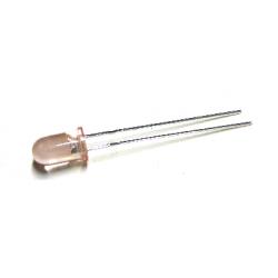
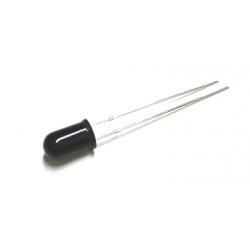
| + | [[File:transmitter-opto.jpg|Transmitter]] [[File:receiver-opto.jpg|Receiver]] | ||
| + | |||
| + | The most common style of optos are the ''Bally/Williams'' '''WPC''' style [https://www.pinballlife.com/index.php?p=product&id=170 opto transmitter] and [https://www.pinballlife.com/index.php?p=product&id=171 receiver], available as an [https://www.pinballlife.com/index.php?p=product&id=168 assembly] ready to use. The LED emitter has no circuitry attached to it by default. | ||
| + | |||
| + | In order to safely power this type of LED, you will need to know the ''forward voltage'' of the LED, the ''maximum constant current'' that the LED can handle, what ''input voltage'' to supply to it (5v or 12v), and how much ''current'' to give the LED to ensure it has enough power to transmit infrared light to reach the opposite opto receiver. | ||
| + | |||
| + | For the ''WPC'' style opto the values are: | ||
| + | |||
| + | * '''Forward Voltage''': 1.7v | ||
| + | * '''Max Constant Current''': 100mA, but it is recommended to not exceed 75mA to maximize the life of the LED. This will be powerful enough to transmit a decent amount of distance between the emitter and receiver. | ||
| + | * '''Input Source Voltage''': 5v DC is recommended as it is higher than the forward voltage of the LED, and low enough that the resistor does not have to dissipate too much heat. | ||
| + | |||
| + | |||
| + | These LED emitters will need a current limiting resistor in series with them as applying 5v or 12v directly to the LED will cause it to overload and fail. Using a [http://led.linear1.org/1led.wiz?VS=5;VF=1.7;ID=75 Resistance Calculator], the resistor value can be easily determined. | ||
| + | |||
| + | '''Important''': Be sure to use at least the minimum recommended resistor wattage. The calculator above is recommending at least a 1/2 watt resistor. Too small of a resistor and it can burn up, | ||
| + | |||
| + | On the receiver end, it can simply be wired directly to the inputs of your switch board. It will behave just like a standard switch as long as it is connected in the correct orientation. The ''cathode'' (ground) side of the emitter is the side with the flat indentation on the black epoxy base. However, note that opto receivers are '''normally closed''' switches and when it detects the IR beam from the emitter, it will be in a closed state, which is the opposite of a normal switch. When a ball breaks the opto beam it will go from a closed state to an '''open''' state, so your software needs to understand this. | ||
| + | |||
| + | ==== Ball Trough ==== | ||
| + | |||
| + | The trough is positioned at the bottom of the playfield and is used to collect all the balls used in standard game play. Originally holding only a single ball, it has evolved over the years and current versions can hold anywhere from one to six balls. | ||
| + | |||
| + | [[Image:ball-trough-example.jpg]] | ||
| + | |||
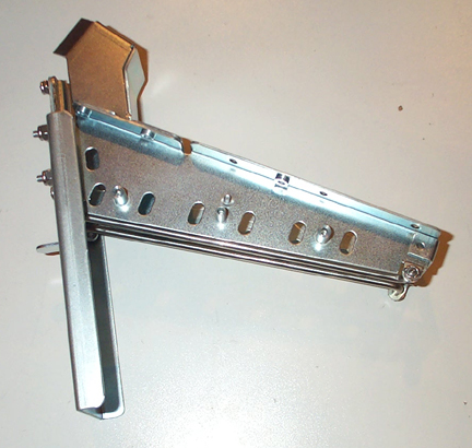
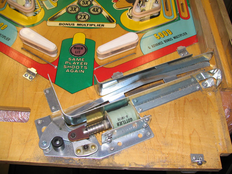
| + | Here is an original '''Gottlieb''' single ball trough: | ||
| + | |||
| + | [[Image:original-trough.jpg|500px]] | ||
| + | |||
| + | Here is an example of a ''Stern'' trough installed on a ''Batman'' playfield: | ||
| + | |||
| + | [[Image:ball-trough-stern.jpg|500px]] | ||
| + | |||
| + | Pinball Life offers an affordable [http://www.pinballlife.com/index.php?p=product&id=4120 trough] that will work well in custom applications. It's available in a 3-ball and 6-ball version. | ||
| + | |||
| + | [[Image:pbl-trough.jpg]] | ||
| + | |||
| + | ==== Slingshots ==== | ||
| + | |||
| + | '''Slingshots''' are the objects above the flippers that kick the ball in the general direction of each other and towards the outlanes due to their upward angle. The lower playfield layout for modern machines has become a standard of two flippers, two outlanes, two inlanes, and two slingshots in a standard layout. | ||
| + | |||
| + | [[Image:slingshots-1.jpg]] | ||
| + | |||
| + | For example, here is a 1977 ''Gottlieb Mustang'' EM game illustrating the standard layout that has remained mostly unchanged in the last 30 years: | ||
| + | |||
| + | [[Image:lower-playfield.jpg|600px]] | ||
| + | |||
| + | The mechanism for slightshots involves a coil under the playfield that fires when a ball hits the rubber ring of the slingshot, closes one of two switches to register the hit, then propelling the ball in the opposite direction. | ||
| + | |||
| + | [[Image:bally-slingshot-diagram.jpg]] | ||
| + | |||
| + | Configuration for slingshots is not limited to just the standard layout, so home builders are free to layout slingshots in whatever manner they like. Occasionally even manufacturers themselves deviate from the standard layout - for example, ''Williams Space Station'' has no inlanes: | ||
| + | |||
| + | [[Image:space-station.jpg]] | ||
| + | |||
| + | ==== Drop Targets ==== | ||
| + | |||
| + | A Drop Target is a flat mechanical target that is held up on a small ledge and when hit with a ball, is moved backwards and dropped down via a small spring. There are generally switches for both the ''Up'' and ''Down'' positions but just a single ''Down'' switch will work. They can be arranged as single targets or in rows. | ||
| + | |||
| + | [[Image:drop-target-row.jpg|500px]] | ||
| + | |||
| + | Every manufacturer has their own designs and use a variety of switch types to detect the target position - ''Williams'' used optos while modern ''Stern'' games use microswitches. | ||
| + | |||
| + | Diagram of a standard ''Williams'' target including a drop coil: | ||
| + | |||
| + | [[Image:drop-target-diagram.png|500px]] | ||
| + | |||
| + | They are also available in an '''Inline''' format. | ||
| + | |||
| + | [[Image:inline-drop-targets.jpg|500px]] | ||
| + | |||
| + | Drop Targets are available in many of the usual mail-order establishments such as [https://www.pinballlife.com/index.php?p=catalog&parent=410 Pinball Life] but usually come in only the standard colors such as Opaque Red, Yellow, Black or White. If you are planning on Back-lighting the drop targets with LEDs for effect or mode selection; Pinball-Mods.com offers Drop Targets in [https://Pinball-Mods.com/url/ClrDropTarget Frosted "Clear" Polycarbonate] for exactly this purpose. Make a [http://pinballmakers.com/wiki/index.php/Construction#Stencil_Cutter custom stencil] and you have a theme specific drop target. | ||
| + | |||
| + | ==== Kickback ==== | ||
| + | |||
| + | The kickback feature in a pinball machine allows the player to continue where they would have otherwise drained out of either outlane. A solenoid fires (not unlike an auto-plunger) against the ball, which quickly shoots it up the outlane and back into the playfield. For many games, this is enabled as part of the ball save and given to the player as a reward during normal play. | ||
| + | |||
| + | [[Image:kickback.jpg]] | ||
| + | |||
| + | The solenoid is mounted in the apron area, and a lane guide will need to be mounted for the ball to properly shoot upward and out. Normally there is a playfield lamp in the outlane to indicate to the player kickback is active. | ||
| + | |||
| + | ==== VUK ==== | ||
| + | |||
| + | Also known as ''Vertical Up-Kicker'', this is a scoop with a vertically mounted coil under the playfield with a plunger that kicks the ball vertically, typically through a scoop to bring a ball from one playfield to a higher one, or bring it up to wireform ramps. Scoop heights can vary, so there is really no stock part that will work in all applications. | ||
| + | |||
| + | Below you can see a VUK scoop made from cardboard, first cut out as a flat sheet, then folded up and glued along the edges (similar to bending sheet metal and tacking the gaps). An even better material to use is [[Construction#Foam_Core|Foam Core]]. | ||
| + | |||
| + | [[Image: Vuk_scoop_flat.jpg|350px]] | ||
| + | [[Image: Vuk_formed.jpg|200px]] | ||
| + | |||
| + | After the scoop has been tested thoroughly (as with any design), it can be transferred to sheet metal and welded, or bent from PETG plastic and glued. Be sure to include tabs for mounting to the playfield. | ||
| + | |||
| + | ==== Pop Bumper Parts ==== | ||
| + | Retail Pop Bumper Bodies are starting to come in nearly every color of the rainbow so you can somewhat easily match to color of bodies to your artwork, pop caps, or intended lighting. | ||
| + | |||
| + | ===== Modern Pop Bumper Parts ===== | ||
| + | Pinball Life sells most standard colors in the [https://www.pinballlife.com/index.php?p=product&id=3945 opaque] category and include Red, Blue, Orange, Yellow, and Black. Additionally PBL sells matching [https://www.pinballlife.com/index.php?p=product&id=3945 Skirts] in those same colors with the addition of Green, Teal, and Purple. | ||
| + | |||
| + | If you'd rather show art thru the pop bumper body, skirts, and bases; Pinball-Mods.com offers translucent [http://Pinball-Mods.com/url/pm_pbumper modern popbodies], [http://Pinball-Mods.com/url/pm_pskirt translucent skirts] and [http://Pinball-Mods.com/url/pm_pbase bases]; you can have artwork under the skirt for that little extra flair. | ||
| + | |||
| + | Try Pinball-Mods.com's [http://Pinball-Mods.com/url/PopBumperCFG?utm_source=pinballmakers Pop Bumper Configurator] to make ordering simple. | ||
| + | |||
| + | [[Image:PopCapModernColors.jpg|240px]] [[Image:TranslucentModernBodies.jpg|240px]] [[Image:SkirtColors.jpg|240px]][[Image:BaseColors.jpg|240px]] | ||
| + | |||
| + | ===== Early SolidState Pop Bumper Parts ===== | ||
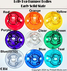
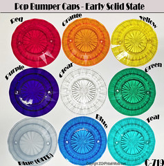
| + | C-114 SolidState bodies are available [http://Pinball-Mods.com/url/C-114Body early solid-state bodies] in 9 different colors including Glow-In-The-Dark Blue. If you use their [http://Pinball-Mods.com/url/pm_pskirt translucent skirts] and [http://Pinball-Mods.com/url/pm_pbase bases]; you can have artwork under the skirt for that little extra flair. Pinball-Mods.com offers both [http://pinball-mods.com/oscom/bumper-modern-p-63.html?utm_source=pinballmakers modern] and [http://Pinball-Mods.com/url/C719SunCap?utm_source=pinballmakers early solid state] Pop Bumper Caps. | ||
| + | |||
| + | Try Pinball-Mods.com's [http://Pinball-Mods.com/url/PopBumperCFG?utm_source=pinballmakers Pop Bumper Configurator] to make ordering simple. | ||
| + | |||
| + | [[Image:C114Body.jpg|240px]] [[Image:C719SunCaps.jpg|240px]] | ||
| + | |||
| + | ===== 80s Bally Thumper Bumper Clip Style Parts ===== | ||
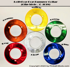
| + | Available in opaque white from the usual vendors or in 6 translucent colors from Pinball-Mods.com [http://pinball-Mods.com/url/C970Body?utm_source=pinballmakers C-970 Clip Body]. The [http://pinball-Mods.com/url/clipCollar?utm_source=pinballmakers Clip Collars] are available in the same colors along with the http://pinball-Mods.com/url/03-8277Cap?utm_source=pinballmakers PopCaps]. | ||
| + | |||
| + | [[Image:C970ClipBody.jpg|240px]] [[Image:C-1018PopCollar.jpg|240px]] [[Image:Clip03-8277Cap.jpg|240px] | ||
| + | |||
| + | ==== Hangers ==== | ||
| + | |||
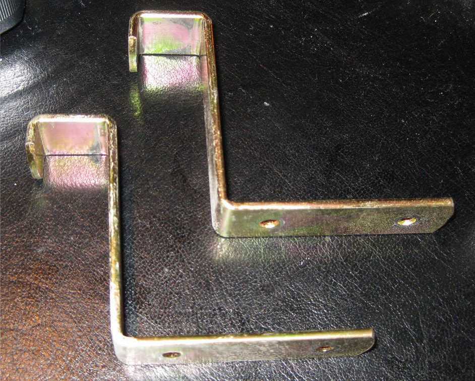
| + | '''Hangers''' (sometimes spelled "hangars") are the brackets at the bottom of the playfield that attach to the lockdown bar mechanism to hold the playfield up. Every manufacturer seems to have slightly different styles. Early ''Williams'' used a Z-shaped bracket that installed from underneath the playfield. | ||
| + | |||
| + | [[Image:williams-hanger.png|400px]] | ||
| + | |||
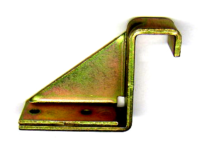
| + | The currently available off-the-shelf bracket is the ''Stern/Sega'' bracket that has a gusset shape, and are mounted above the playfield rather than below. | ||
| + | |||
| + | [[Image:Stern_gusset_hanger.jpg]] | ||
| + | |||
| + | === Switch Types === | ||
| + | |||
| + | There are a number of options when selecting switches, all of which have been used in pinball machines over the years. | ||
| + | |||
| + | A '''Leaf''' switch consists of two metal blades held together in a contact assembly, with one of the blades generally being longer than the other. In a normally-open leaf switch, the longer blade is pushed toward the shorter blade to close the circuit. On a modern pinball machine, only normally-open switches are used. | ||
| + | |||
| + | [[Image:switch-1.gif|300px]] | ||
| + | |||
| + | Translucent Colored switch blade targets are available at both [https://www.pinball.center/en/search?sSearch=transparent+target Pinball.Center] (for europe) and [https://Pinball-Mods.com/url/StationaryTargets Pinball-Mods.com] in North America. Available in 9 colors so they can be matched to any art style on your custom game. | ||
| + | |||
| + | [[Image:LollyPopStationaryTargets.jpg]] | ||
| + | |||
| + | A '''Microswitch''' is a small enclosed switch that has a sheet metal blade or wire actuator to operate the switch. The actuator is not electrically connected to the switch contacts, so it can be used in situations where directly moving one of the switch leaves would be dangerous. The blade or wire actuator can be bent into a convenient shape for the game requirements | ||
| + | |||
| + | Microswitches with wire actuators are used for playfield roll-overs. The wire is bent to stick up through a slot in the playfield. When the ball rolls over the wire, it pushes down on the wire which operates the switch. Ones with blade actuators are used for detecting a ball passing through a gate. As the ball moves the wire gate, one end of the wire swivels down to press the blade which operates the switch. | ||
| + | |||
| + | [[Image:switch-3.gif]] [[Image:switch-2.gif]] | ||
| + | |||
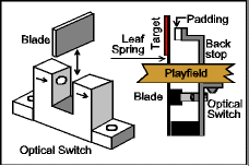
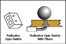
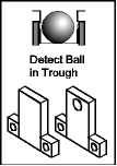
| + | '''Optical''' switches use an infra-red light emitting diode (LED) to activate a photo transistor. There are three variations that are useful in pinball machines: | ||
| + | |||
| + | [[Image:switch-4.gif]] [[Image:switch-5.gif]] [[Image:switch-6.gif]] | ||
| + | |||
| + | * '''Slot-Type''': A slot-type optical switch has the LED and the photo transistor mounted in the legs of a "U" shaped plastic. The light emitting diode is always on, and a "blade" that moves in and out of the slot interrupts the beam turning the photo transistor on and off. | ||
| + | * '''Reflective''': An optical switch that has the LED and the photo transistor mounted side-by-side and facing outward. When a reflective surface comes near the switch, the beam from the LED reflects back to the photo transistor. Typical range for this type of switch is 3-6 millimeters or 1/8" to 1/4". | ||
| + | * '''Separates''': An optical switch that has the LED and photo transistors in separate packages. The light emitting diode is always on, and an object moving between the LED and the photo transistor interrupts the beam turning the photo transistor on and off. The range for this type of switch can be up to 30 centimeters or 12". | ||
| + | |||
| + | |||
| + | '''Proximity''' switches may be ''inductive, ultrasonic, capacitive, or optical''. A proximity switch detects the presence or absence of something within a certain ''proximity'' (or range) of the switch. | ||
| + | |||
| + | '''Inductive''' proximity switches work in two different ways. The '''Active''' type, an oscillator generates an electromagnetic field. When an electrically or magnetically conductive object enters the field of the oscillator, its frequency is altered, and the output switches. This type of switch can only be used when oscillator field will not sense too large an area. The '''Passive''' type uses a coil with an iron core or a semiconductor in a magnetic field (Hall effect sensor). A moving, magnetically conductive object disturbs the magnetic field and generates an electric current. This type of switch is not sensitive enough to detect a pinball reliably. It is used for detecting regular movement like gear wheel teeth rotating past, or with a magnet in a keyboard switch. | ||
| + | |||
| + | '''Capacitive''' proximity switches work in two different ways. The '''Passive''' type has a sensor that consists of two concentrically mounted electrodes (which are the electrodes of an opened capacitor). When an object approaches the sensor, the electrostatic field is changed. (It changes in opposite directions for conductive and non-conductive materials.) This change is detected by the switch. The '''Active''' type capacitive switches operate by generating a radio frequency. As an object approaches, the impedance seen by the radio frequency changes. This influence is measured within the circuitry and compared with the reference point set by the sensitivity adjustment. | ||
| + | |||
| + | The key factor for a switch is that it ''electrically completes a circuit'', so they can consist of any two conductive objects being connected - so, even the pinball itself can be used as a switch if it connect two wires together! | ||
== Whitewood == | == Whitewood == | ||
| Line 172: | Line 372: | ||
Typically a playfield is made of 9-ply birch plywood, '''17/32"''' thick with the additional 1/32" allowing for the inserts to be sanded flush. A number of European manufacturers used plastic playfields, and some domestic companies experimented with them in the 1970's, but the vast majority use plywood. | Typically a playfield is made of 9-ply birch plywood, '''17/32"''' thick with the additional 1/32" allowing for the inserts to be sanded flush. A number of European manufacturers used plastic playfields, and some domestic companies experimented with them in the 1970's, but the vast majority use plywood. | ||
| − | === | + | ===Playfield Sizes=== |
| + | Here is a list of playfield sizes by various manufacturers; | ||
| − | + | {|class="wikitable" style="border-width: 5px;" cellpadding="10" | |
| + | !Company | ||
| + | !Type | ||
| + | !Style | ||
| + | !Inches | ||
| + | |- | ||
| + | |Alvin G | ||
| + | |SS | ||
| + | |Standard | ||
| + | |20.25" x 42.00" | ||
| + | |- | ||
| + | |Alvin G | ||
| + | |SS | ||
| + | |Mystery Castle | ||
| + | |20.25" x 46.00" | ||
| + | |- | ||
| + | |Atari | ||
| + | |SS | ||
| + | |Widebody | ||
| + | |27.00" x 45.00" | ||
| + | |- | ||
| + | |Bally | ||
| + | |EM | ||
| + | |Standard | ||
| + | |20.25" x 41.00" | ||
| + | |- | ||
| + | |Bally | ||
| + | |SS | ||
| + | |Standard | ||
| + | |20.25" x 42.00" | ||
| + | |- | ||
| + | |Bally | ||
| + | |SS | ||
| + | |Widebody | ||
| + | |26.75" x 40.50" | ||
| + | |- | ||
| + | |Capcom | ||
| + | |SS | ||
| + | |Standard | ||
| + | |20.25" x 46.00" | ||
| + | |- | ||
| + | |Data East | ||
| + | |SS | ||
| + | |Standard | ||
| + | |20.25" x 46.00" | ||
| + | |- | ||
| + | |Data East | ||
| + | |SS | ||
| + | |Widebody | ||
| + | |25.00" x 51.75" | ||
| + | |- | ||
| + | |Game Plan | ||
| + | |SS | ||
| + | |Standard | ||
| + | |20.25" x 42.00" | ||
| + | |- | ||
| + | |Gottlieb | ||
| + | |EM | ||
| + | |Standard | ||
| + | |20.25" x 41.00" | ||
| + | |- | ||
| + | |Gottlieb | ||
| + | |System 1 | ||
| + | |Standard | ||
| + | |20.25" x 42.00" | ||
| + | |- | ||
| + | |Gottlieb | ||
| + | |System 80 | ||
| + | |Standard | ||
| + | |20.25" x 42.00" | ||
| + | |- | ||
| + | |Gottlieb | ||
| + | |System 80 | ||
| + | |Widebody | ||
| + | |23.75" x 46.50" | ||
| + | |- | ||
| + | |Gottlieb | ||
| + | |System 80 | ||
| + | |Circus (Extra Wide) | ||
| + | |26.75" x 46.50" | ||
| + | |- | ||
| + | |Gottlieb | ||
| + | |System 3 | ||
| + | |Standard | ||
| + | |20.25" x 46.00" | ||
| + | |- | ||
| + | |Stern Electronics | ||
| + | |SS | ||
| + | |Standard | ||
| + | |20.25" x 42.00" | ||
| + | |- | ||
| + | |Stern Electronics | ||
| + | |SS | ||
| + | |Widebody | ||
| + | |23.875" x 45.00" | ||
| + | |- | ||
| + | |Stern Pinball | ||
| + | |SS | ||
| + | |Standard | ||
| + | |20.25" x 45.00" | ||
| + | |- | ||
| + | |Williams | ||
| + | |System 1-11 | ||
| + | |Standard | ||
| + | |20.25" x 42.00" | ||
| + | |- | ||
| + | |Williams | ||
| + | |System 1-11 | ||
| + | |Widebody | ||
| + | |27.00" x 42.00" | ||
| + | |- | ||
| + | |WMS | ||
| + | |WPC | ||
| + | |Safecracker | ||
| + | |16.50" x 41.50" | ||
| + | |- | ||
| + | |WMS | ||
| + | |WPC (through 1987) | ||
| + | |Standard | ||
| + | |20.50" x 42.00" | ||
| + | |- | ||
| + | |WMS | ||
| + | |WPC (1987 on) | ||
| + | |Standard | ||
| + | |20.25" x 44.5" | ||
| + | |- | ||
| + | |WMS | ||
| + | |WPC | ||
| + | |Superpin (Widebody) | ||
| + | |23.00" x 46.00" | ||
| + | |- | ||
| + | |WMS | ||
| + | |Pinball 2000 | ||
| + | |Standard | ||
| + | |20.50" x 43.00" | ||
| + | |- | ||
| + | |Zaccaria | ||
| + | |SS | ||
| + | |Standard | ||
| + | |20.25" x 42.00" | ||
| + | |} | ||
=== Foam Core === | === Foam Core === | ||
| Line 191: | Line 532: | ||
[[Image:foam-core-2.jpg|500px]] | [[Image:foam-core-2.jpg|500px]] | ||
| + | |||
| + | An alternate to foam core (which can be pricey at $7 for a 2' x 3' sheet), is cardboard. It is a material that is readily available in multiple thicknesses and footprint sizes, often obtainable for free since it's such a highly recycled material. It can be bent at angles and remain stiff in fluted versions, or bent in a curve by squishing the flutes down, very similarly to sheet metal. Since cardboard has no foam inside, it can often be stiffer and closer to a harder material like plastic. It is as easily cut with an x-acto blade or scissors. | ||
=== Cutting === | === Cutting === | ||
| Line 242: | Line 585: | ||
[[Image:cabinet-parts.jpg|500px]] | [[Image:cabinet-parts.jpg|500px]] | ||
| + | |||
| + | Alternatively, for just the playfield mounting parts: | ||
| + | |||
| + | * 2x [https://www.pinballlife.com/stern-playfield-pivot-bracket-500-5329-03.html Stern Playfield Pivot Bracket 500-5329-03] | ||
| + | * 2x [https://www.pinballlife.com/stern-edge-slide-bracket.html Stern Edge Slide Bracket] | ||
| + | * 1x [https://www.pinballlife.com/stern-slide-pivot-support-bracket-right.html Stern Slide & Pivot Support Bracket - Right] | ||
| + | * 1x [https://www.pinballlife.com/stern-slide-pivot-support-bracket-left.html Stern Slide & Pivot Support Bracket - Left] | ||
| + | * 2x [https://www.pinballlife.com/stern-playfield-hanger-bracket.html Stern Playfield Hanger Bracket] | ||
| + | * 1x [https://www.pinballlife.com/williamsbally-lockdown-bar-lever-guide-receiver-assembly-wpcwpc-95.html WMS Lockdown Bar Lever Guide Receiver Assembly] | ||
| + | * 1x [https://www.pinballlife.com/williamsbally-standard-size-stainless-steel-lockdown-bar-circa-1990-1998-seconds.html WMS Standard Size Stainless Steel Lockdown Bar] | ||
| + | |||
When cutting your cabinet for the coin door, keep in mind it is installed with four bolts centered on the bottom, sides and top, and that the top hole goes through the lockdown bracket. So both need to line up. | When cutting your cabinet for the coin door, keep in mind it is installed with four bolts centered on the bottom, sides and top, and that the top hole goes through the lockdown bracket. So both need to line up. | ||
[[Image:coin-door-lockdown.jpg|500px]] | [[Image:coin-door-lockdown.jpg|500px]] | ||
| + | |||
| + | === Off-the-shell Cabinet Parts === | ||
| + | Custom pinball machine cabinets is becoming easier due to many vendors providing "mod" friendly cabinet parts. | ||
| + | |||
| + | ==== Flipper Buttons ==== | ||
| + | |||
| + | [[Image:Pbl_a-16883.jpg|150px]] | ||
| + | Pinball-Life sells both [http://www.pinballlife.com/index.php?p=product&id=1692 opaque] and [http://www.pinballlife.com/index.php?p=product&id=3332 translucent] modern flipper buttons compatible with Stern and late model Williams cabinets. | ||
| + | |||
| + | [[Image:Pinball-Mods_com_Buttons.jpg|150px]] [[Image:Pinball-Mods_com_Housings.jpg|150px]] | ||
| + | |||
| + | Pinball-Mods.com offers both the [http://Pinball-Mods.com/url/pm_btns Buttons] and [http://Pinball-Mods.com/url/pm_btnhouse Housings] for early solid state machine cabinets by Bally, Gottlieb, Stern, and Chicago Coin which can be lit with LEDs using a technique documented in a [http://pinside.com/pinball/forum/topic/classic-bally-stern-clear-buttons-vids-review Pinside thread]. | ||
== Electronics == | == Electronics == | ||
| Line 261: | Line 627: | ||
=== Custom Boards === | === Custom Boards === | ||
| + | * '''[[OPP|Open Pinball Project]]''' is a low-cost, DIY solution for basic pinball control and is a good way to learn pinball control systems. There is extensive documentation hosted on this wiki. | ||
* '''[https://github.com/LonghornEngineer/Pinheck_Pinball_System Pinheck]''' is a system designed by Ben Heck for use in America's Most Haunted and is not currently available in kit form, but you can download the design and have it printed yourself for use in your own games. | * '''[https://github.com/LonghornEngineer/Pinheck_Pinball_System Pinheck]''' is a system designed by Ben Heck for use in America's Most Haunted and is not currently available in kit form, but you can download the design and have it printed yourself for use in your own games. | ||
* '''[https://github.com/stu/system_shock System Shock]''' is a work-in-progress and currently only the driver board is available for download. | * '''[https://github.com/stu/system_shock System Shock]''' is a work-in-progress and currently only the driver board is available for download. | ||
| Line 267: | Line 634: | ||
* '''[http://www.pinballcontrollers.com/index.php/products/p-roc P-ROC]''' (Pinball - Remote Operations Controller) is a well-supported generic platform that is in use by many custom games. It has a dedicated [http://www.pinballcontrollers.com/forum/ forum]. | * '''[http://www.pinballcontrollers.com/index.php/products/p-roc P-ROC]''' (Pinball - Remote Operations Controller) is a well-supported generic platform that is in use by many custom games. It has a dedicated [http://www.pinballcontrollers.com/forum/ forum]. | ||
| − | * '''[http://fastpinball.com/ FAST Pinball]''' | + | * '''[http://fastpinball.com/ FAST Pinball]''' has controllers and board comparable to P-ROC. |
| − | * '''[ | + | * '''[https://pinballmakers.com/wiki/index.php?title=CobraPin CobraPin Pinball Controller]''' Is a fully assembled control solution based on the infrastructure of OPP. |
=== Controller PCs === | === Controller PCs === | ||
| Line 277: | Line 644: | ||
* '''[http://beagleboard.org/BLACK Beaglebone Black]''': AM335x 1GHz ARM® Cortex-A8, 512MB DDR3 RAM, 4GB 8-bit eMMC on-board flash storage | * '''[http://beagleboard.org/BLACK Beaglebone Black]''': AM335x 1GHz ARM® Cortex-A8, 512MB DDR3 RAM, 4GB 8-bit eMMC on-board flash storage | ||
* '''[http://cubieboard.org/model/cb3/ CubieTruck]''': ARM® Cortex™-A7 Dual-Core, 2GB DDR3, HDMI & VGA 1080P display output, 10M/100M/1G Ethernet, Wifi + BT, SATA 2.0 , NAND+MicroSD or TSD+ MicroSD or 2*MicroSD | * '''[http://cubieboard.org/model/cb3/ CubieTruck]''': ARM® Cortex™-A7 Dual-Core, 2GB DDR3, HDMI & VGA 1080P display output, 10M/100M/1G Ethernet, Wifi + BT, SATA 2.0 , NAND+MicroSD or TSD+ MicroSD or 2*MicroSD | ||
| + | |||
| + | === Coil Sizes === | ||
| + | |||
| + | [[Image:coil.jpg]] | ||
| + | |||
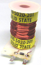
| + | When choosing coils, it is important to understand how coil sizing works. | ||
| + | |||
| + | For example, decoding the ''Williams'' part number '''AL-23-550''' has three parts - the prefix '''AL''' means the coil has base wire lugs on the left and middle of the coil's base, while '''23''' is 23 gauge wire and '''550''' is the number of turns of wire. The more turns, the weaker the coil. | ||
| + | |||
| + | For more details on coils, check out the [http://www.pinballmedic.net/coil_chart.html Pinball Medic coil chart]. | ||
=== Power Supplies === | === Power Supplies === | ||
| Line 289: | Line 666: | ||
* '''[http://www.digikey.com/product-search/en?x=18&y=17&lang=en&site=us&keywords=285-1815-ND TDK-Lamda]''': Available from ''Digikey''. Model '''LS150-36''' is a '''36V''' switching supply, suitable for most standard coils but may not be enough for flippers or VUKs. | * '''[http://www.digikey.com/product-search/en?x=18&y=17&lang=en&site=us&keywords=285-1815-ND TDK-Lamda]''': Available from ''Digikey''. Model '''LS150-36''' is a '''36V''' switching supply, suitable for most standard coils but may not be enough for flippers or VUKs. | ||
* '''[http://www.jameco.com/webapp/wcs/stores/servlet/Product_10001_10001_295929_-1 Meanwell]''': The '''SE-600-48''' is a '''48V 12A''' supply which can be dialed up to 50v. There are also lower amperage 48V models such as the '''Meanwell NES-350-48''' which provides '''7A'''. Meanwell is a highly respected brand that make very good power supplies. | * '''[http://www.jameco.com/webapp/wcs/stores/servlet/Product_10001_10001_295929_-1 Meanwell]''': The '''SE-600-48''' is a '''48V 12A''' supply which can be dialed up to 50v. There are also lower amperage 48V models such as the '''Meanwell NES-350-48''' which provides '''7A'''. Meanwell is a highly respected brand that make very good power supplies. | ||
| − | * '''[http://www.ebay.com/sch/i.html?_from=R40&_trksid=cnc+power+supply&_nkw=cnc+power+supply&_sacat=0 eBay]''': Search for ''CNC Power Supplies''. These will often be '''48V''' high current switching supplies designed for stepper motors and | + | * '''[http://www.ebay.com/sch/i.html?_from=R40&_trksid=cnc+power+supply&_nkw=cnc+power+supply&_sacat=0 eBay]''': Search for ''CNC Power Supplies''. These will often be '''48V''' high current switching supplies designed for stepper motors and will provide enough power for coils so long as the maximum current isn't exceeded. |
| + | |||
| + | ==== Selecting Power Supplies ==== | ||
| + | |||
| + | It is recommended to get at least a '''3A''' supply for coils. The quality, especially from China, is not always guaranteed. Be sure to choose one with a case that has adequate venting to prevent shorts if any metal items are dropped on the circuitry. Power supplies with fans are recommended. They typically won't turn on unless they get hot enough (Coils pulling excessive current, hot ambient temperature). Sometimes coils may pull more amps than the power supply can provide, so wiring in resistors and capacitors (to buffer energy) may be necessary so the power supply doesn't reset. | ||
| + | |||
| + | Computer power supplies are fine for CPU and some lighting, but won't provide enough current for solenoids. If using a standard PC as the CPU for the machine, there is a useful [http://scottdanesi.com/WP/?page_id=398 board] for controlling PC power supplies from the external high-current supply. | ||
| + | |||
| + | With modern switching power supplies, having one supply for coils and another for CPU / LEDs is common, so please remember that '''All grounds from all supplies need to be connected together''' otherwise it may create a '''floating ground''' situation that can lead to destroying boards and other electronics. | ||
| + | ==== Capacitor / Filter Board ==== | ||
| − | + | Using a modern switcher with coils means using a '''Capacitor Board''' between the supply and any solenoids to provide coils that sudden onrush of current. Some options include: | |
| − | + | [[Image:power-entry.png|Power Entry PCB]] | |
| + | |||
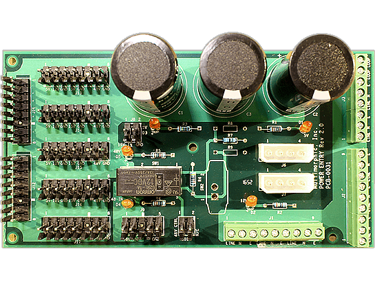
| + | The Multimorphic [https://www.multimorphic.com/store/circuit-boards/power-entry/ Power Entry PCB] distributes AC power and up to 4 different DC voltages, generally 5v, 12v, 15v, and “high voltage” (typically 48v or 70v). A 12v relay enables the “high voltage” output. LEDs identify the presence of each of the 4 DC voltages. | ||
| + | |||
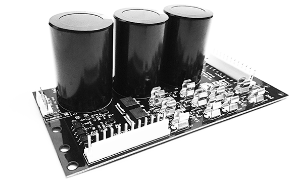
| + | [[Image:fast-power.png|FAST Power Filter Board]] | ||
| + | |||
| + | The FAST [http://fastpinball.com/platform/hardware/fast-power/fast-power-filter-board Power Filter Board] provides capacitor filtering and fusing. | ||
| + | |||
| + | For those interested in DIY solutions, the OPP [[OPP#Power_Filter_Board|Power Filter Board]] provides similar functionality. | ||
== Wiring == | == Wiring == | ||
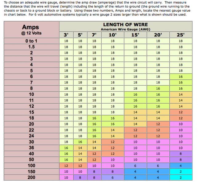
Most pinball machines have wire harnesses of some type. As high-current devices, solenoids typically need a minimum of '''18AWG''' wire. Wiring for lighting and switches can be much thinner since it's pulling less current, particularly if using LEDs, so '''20-22AWG''' wiring is acceptable for low-current uses. | Most pinball machines have wire harnesses of some type. As high-current devices, solenoids typically need a minimum of '''18AWG''' wire. Wiring for lighting and switches can be much thinner since it's pulling less current, particularly if using LEDs, so '''20-22AWG''' wiring is acceptable for low-current uses. | ||
| + | |||
| + | [[Image:wire-guages.png]] | ||
| + | |||
| + | === Connectors === | ||
| + | |||
| + | Most Pinball machines use the [https://www.molex.com/product/kk/kk.html Molex KK Series] connectors in the '''0.100"''' and '''0.156"''' sizes. There is a PDF with the part numbers from Mouser in the [[Files_Section|Files]] section. | ||
=== Wire Management === | === Wire Management === | ||
| Line 313: | Line 713: | ||
[[Image:wire-manage-3.jpg|400px]] | [[Image:wire-manage-3.jpg|400px]] | ||
| + | |||
| + | === Wiring Harness === | ||
| + | |||
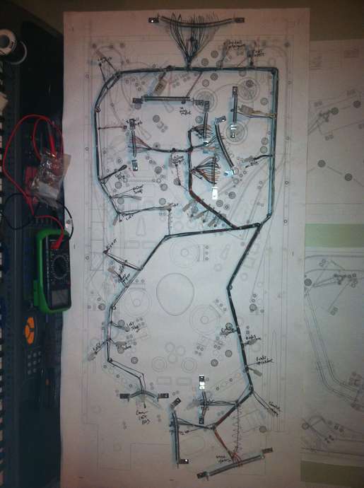
| + | Once the final wiring layout is complete, paper templates of the playfield layout on thick cardboard or wood paneling can be used to make a '''Wiring Pinboard''', similar to the boards that the manufacturers use to make their '''Wiring Harnesses'''. Place nails in appropriate spots and run wires as needed, with tie-wraps. | ||
| + | |||
| + | [[Image:wiring-pinboard-2.jpg|400px]] [[Image:wiring-pinboard.jpg|600px]] | ||
=== Color Coding === | === Color Coding === | ||
| Line 394: | Line 800: | ||
== Lighting == | == Lighting == | ||
| + | |||
| + | Pinball lighting comes in two varieties - ''incandescent'' and ''LED''. Older incandescent games can be retrofitted with modern LED lamps, or when fully customizing, replaced with custom board-mounted LEDs or [http://pinballmakers.com/wiki/index.php/Basics#Serial_Chain_LEDs Serial Chain LEDs]. | ||
=== Socket Styles === | === Socket Styles === | ||
| − | + | For incandescent, most lighting is socketed either by a '''bayonet''' or '''wedge''' socket. | |
[[Image:wedge-base.jpg]] | [[Image:wedge-base.jpg]] | ||
| Line 410: | Line 818: | ||
* Less damaging. The constant heat/cool from incandescent bulbs are known to warp plastics and cause flaking on backglasses. | * Less damaging. The constant heat/cool from incandescent bulbs are known to warp plastics and cause flaking on backglasses. | ||
| − | === Bulb Types === | + | <br />Recently; Pinball.Center and Pinball-Mods.com began offering [http://pinball-mods.com/url/FlashLampSocket Lollypop wedge bases] for use on Ramps and other Plastics. Offered in 7 modder friendly colors. |
| + | |||
| + | === Bulb Mount Types === | ||
The most common sizes are the '''#44/#47 Bayonet''' Base, the '''#555 Wedge''' Base, the '''#89 Bayonet''' and the '''#906 Wedge'''. | The most common sizes are the '''#44/#47 Bayonet''' Base, the '''#555 Wedge''' Base, the '''#89 Bayonet''' and the '''#906 Wedge'''. | ||
| Line 422: | Line 832: | ||
Modern ''Stern'' games going forward use a '''Surface Mount LED''' board that are driven directly which eliminates the need for sockets altogether. The drawback to these are that the boards are directly soldered, so if there are issues, they can't be easily replaced. However, the long life of LEDs makes it unlikely for them to burn out at the rate incandescent lamps do. | Modern ''Stern'' games going forward use a '''Surface Mount LED''' board that are driven directly which eliminates the need for sockets altogether. The drawback to these are that the boards are directly soldered, so if there are issues, they can't be easily replaced. However, the long life of LEDs makes it unlikely for them to burn out at the rate incandescent lamps do. | ||
| − | For a custom game, a combination of '''Cointaker [http://shop.cointaker.com/category.sc?categoryId=211 Premium Frosted]''' or '''Ablaze [http://www.pinballlife.com/index.php?p=product&id=2561 4-LED]''' for GI and the '''FAST Pinball [https://squareup.com/market/fast-pinball-llc/fast-rgb-led-insert RGB LED Insert]''' boards for inserts are a good choice. | + | For a custom game, a combination of '''Cointaker [http://shop.cointaker.com/category.sc?categoryId=211 Premium Frosted]''' or '''Ablaze [http://www.pinballlife.com/index.php?p=product&id=2561 4-LED]''' for GI and the '''FAST Pinball [https://squareup.com/market/fast-pinball-llc/fast-rgb-led-insert RGB LED Insert]''' or '''Multimorphic [https://www.multimorphic.com/store/circuit-boards/rgb-led/ RGB LED]''' boards for inserts are a good choice. |
| − | === | + | === Custom LED Boards === |
| − | + | Many vendors provide custom lighting solutions which might not fit in a traditional socket as above or have specific pinball specific uses. | |
| − | + | [[Image:brite-cap.png|300px|BriteCaps EVO]] | |
| − | [ | + | One example is the [http://www.pinballlife.com/index.php?p=product&id=3624 BriteCaps EVO] mod for #555 Pop bumpers. These PCBs plug into the #555 socket typically found in most modern pop bumper assemblies. |
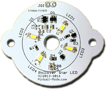
| − | + | [[Image:Pinball-Mods_com_StarRolloverLED.png|300px|Star Rollover LED]] | |
| − | [[Image:lit-flip-2.jpg]] | + | Pinball Mods offers a [http://Pinball-Mods.com/url/StarRolloverLED Star Rollover LED] which shines 4 LEDs from the underside of a [http://www.pbresource.com/bigindian/gtb-d11966c.jpg star rollover] and has a hole in the center to allow the switch actuator to function properly on the leaf switch. |
| + | |||
| + | [[Image:lit-flip-2.jpg|300px|Light up Flipper buttons]] | ||
| + | |||
| + | For lighting translucent flipper buttons, a #44 socket and the Cointaker '''[http://shop.cointaker.com/category.sc;jsessionid=7A7CECA77E05B788FA02BB59CAE187C7.m1plqscsfapp05?categoryId=166 44/47 Flex Super Bright]''' lamps can be installed by attaching the socket under the flipper button and out of the way of the Flipper Button Leaf Switch. Comet Pinball also offers a light up kit for both modern and early solidstate [https://www.cometpinball.com/products/illuminated-flipper-button-kit flipper buttons]which includes the buttons, wiring,m and leds. | ||
| + | |||
| + | [[Image:Pinball-Mods_com_FlipperMod.gif|200px|Flipper Mod]] | ||
| + | |||
| + | Pinball Mods offers the '''[http://Pinball-Mods.com/url/FlipperBtnMod Flipper Button Mod]''' which displays a rotating 12 LED pattern behind early solid state Flipper buttons for project using the [http://pinballmakers.com/wiki/index.php/Construction#Flipper_Buttons older style flipper buttons]. | ||
== Custom Parts == | == Custom Parts == | ||
Many hobbyists plan on producing games with game-specific features that aren't included in other machines, such as ramps or ball control devices, and thus will have to design and construct mechanisms from scratch. This generally involves metalworking, welding and other more advanced skills, but are not beyond the garage hobbyist. | Many hobbyists plan on producing games with game-specific features that aren't included in other machines, such as ramps or ball control devices, and thus will have to design and construct mechanisms from scratch. This generally involves metalworking, welding and other more advanced skills, but are not beyond the garage hobbyist. | ||
| + | |||
| + | === Plastics === | ||
| + | |||
| + | There will likely be many plastic shields scattered on the playfield to: | ||
| + | |||
| + | * Hide mechanisms | ||
| + | * Improve aesthetics | ||
| + | * Prevent a launched ball from getting stuck in a crevice | ||
| + | |||
| + | |||
| + | While using a laser cutter would be ideal, it is possible to produce plastics with basic hand tools. It is recommended to buy something easier to cut than acrylic, such as ''1/16" PETG'', which can be purchased from [http://www.mcmaster.com/#petg/=xs5xgh McMaster]. This can be cut fairly easily with strong scissors (or an x-acto if used carefully), and like acrylic it can be flame polished. | ||
| + | |||
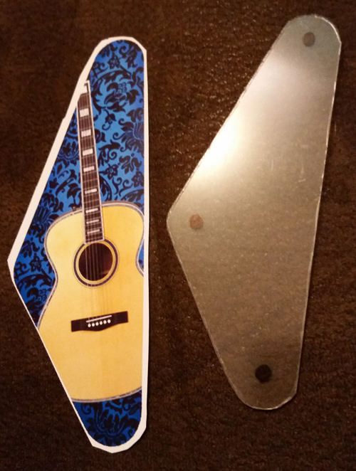
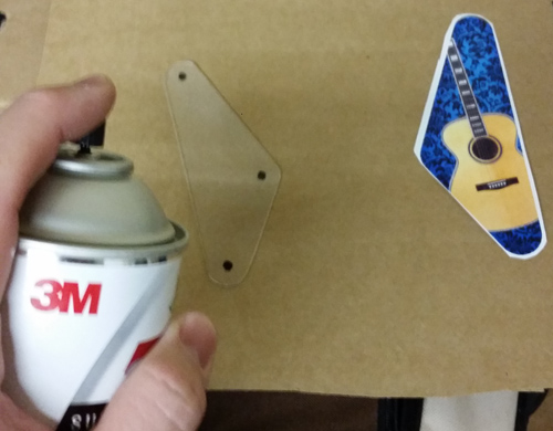
| + | To create artwork, the best method is to print it on ''photo paper'', and then use a ''spray adhesive'' to attach it to the bottom of the plastic. Examples include ''3M Super 77'' (try to find the 25% lower VOC verison). These products dry clear and will not yellow. | ||
| + | |||
| + | [[Image: Spray_adhesive_3m.jpg]] | ||
| + | |||
| + | '''Please use caution when using this product as it is extremely volatile!''' | ||
| + | |||
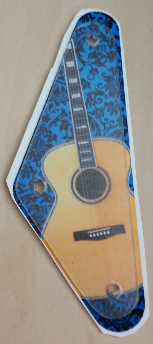
| + | First, trace the shape to be cut on the thin blue film on top of the plastic. Remove the film from the bottom where art is being applied. The artwork should be just slightly bigger than the plastic to ensure there are no gaps when trimmed. | ||
| + | |||
| + | [[Image: Plastics_overlap1.jpg|300px]] | ||
| + | |||
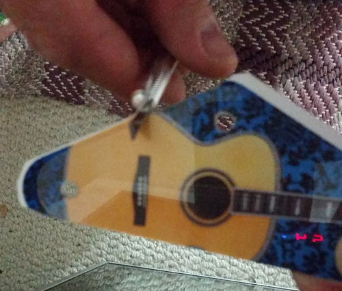
| + | Make sure to spray in light, even coats on the backside of the plastic. Let it get tacky for 10-15 seconds, then move the printed art (art side up) over, and turn the plastic over and apply the plastic onto the paper - this will make it easier to line it up. | ||
| + | |||
| + | [[Image: Plastics_spray2.jpg]] | ||
| + | |||
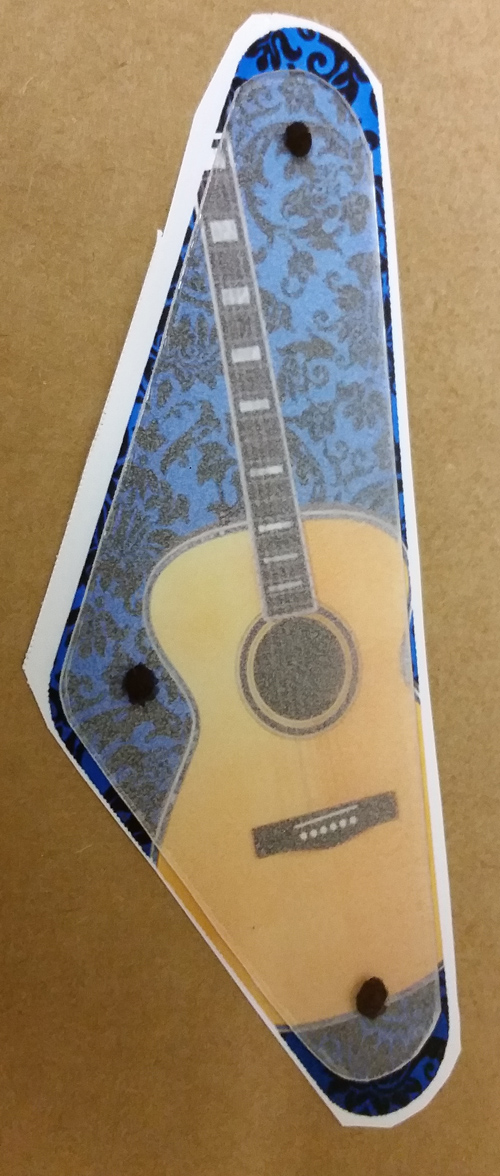
| + | This is what it will look like when first applied. The adhesive will turn clear as it dries. | ||
| + | |||
| + | [[Image: Plastics_apply3.jpg|300px]] | ||
| + | |||
| + | Once the adhesive has dried, the holes can be drilled starting with a small bit, and working up to the hole size needed. | ||
| + | |||
| + | [[Image: Plastics_hole_drill4.jpg|300px]] | ||
| + | |||
| + | Trim off the excess paper by using the plastic as a guide. Trim slow and carefully as to not dig into the plastic with the knife. | ||
| + | |||
| + | [[Image: Plastics_trim5.jpg|300px]] | ||
| + | |||
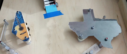
| + | Here's an example of prototyped plastics installed on the slingshots: | ||
| + | |||
| + | [[Image: Plastics_installed6.jpg]] | ||
| + | |||
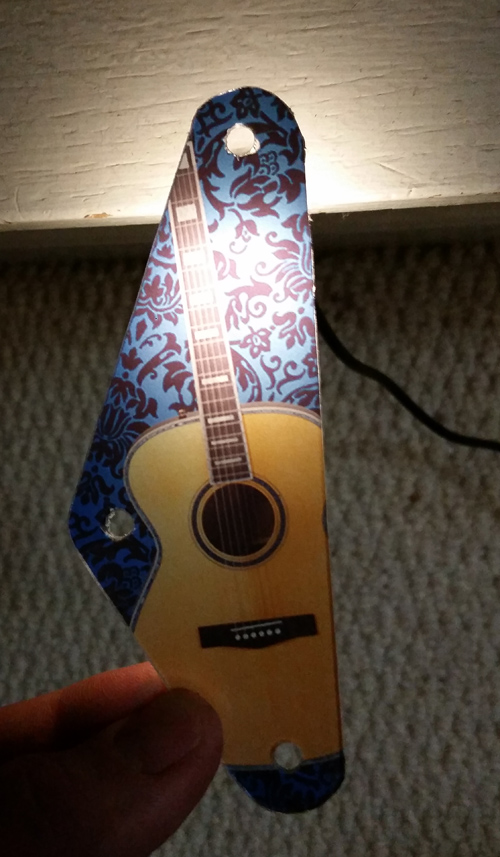
| + | The white paper acts as a nice diffuser to spread the light out, just like the white ink layer on screenprinted plastics. | ||
| + | |||
| + | [[Image: Plastics_lit_up7.jpg|300px]] | ||
=== 3D Printing === | === 3D Printing === | ||
| Line 464: | Line 927: | ||
For most of what a garage builder will do, FDM and home printing will cover it. If a full color print or some very fine details are needed, like screw threads, the part can be ordered from ''Shapeways''. | For most of what a garage builder will do, FDM and home printing will cover it. If a full color print or some very fine details are needed, like screw threads, the part can be ordered from ''Shapeways''. | ||
| − | If planning to purchase a home printer, it is recommended to read the [http://makezine.com/volume/guide-to-3d-printing-2014/ Make Guide to 3D printers]. One option is the '''[http://printrbot.com/shop/simple-metal-kit-with-heated-bed/ Printrbot Simple Metal Kit]''' with a Heated Bed upgrade. | + | If planning to purchase a home printer, it is recommended to read the [http://makezine.com/volume/guide-to-3d-printing-2014/ Make Guide to 3D printers]. One option is the '''[http://printrbot.com/shop/simple-metal-kit-with-heated-bed/ Printrbot Simple Metal Kit]''' with a Heated Bed upgrade. There are many clones coming out now that patents have run out. If you look at the flashforge, there are 2-3 clones that are as cheap as half cost. Monoprice has a few options. While heated bed isn't necessary for PLA, heat does seem to help all materials and is necessary for ABS. Choice of materials will come down to nozzle temp, but you want one that can handle at least 230C or higher. |
| + | |||
[[Image:3d-2.jpg]] | [[Image:3d-2.jpg]] | ||
| Line 514: | Line 978: | ||
[[Image:3d-7.jpg]] | [[Image:3d-7.jpg]] | ||
| + | |||
| + | While all 3d printers should be monitored, once the first few layers stick it's generally safe for them to run un-monitored. PEI sheet beds help sticking, as do things like buildtak and zebra bed. This is much more convenient than replacing blue tape every build. As of this writing, there has never been a 3d printer reported to have thermal runaway and melt. Not to say electronics can't fail, but it's very unlikely. It's not uncommon for users to run batch print jobs overnight while they sleep. Some users have experimented with running jobs while not at home, but this usually requires both a webcam to monitor the print job, and a remote shutdown circuit that is internet enabled through a simple computer like arduino or a raspberry pi. | ||
| + | |||
| + | Software can make a big difference not only in build quality, but build support breakaway. Pay Programs like Simplify3d are not only superior in both of these, but it also spits out g-code very quickly. It also keeps updating with default printer settings as new printers come out. For free software, Cura seems to be the #1 choice. | ||
=== Vacuum-Forming === | === Vacuum-Forming === | ||
| Line 698: | Line 1,166: | ||
To see these parts powder coated and installed, see the ''DeadPin'' machine in the [[Custom_Games]] section. | To see these parts powder coated and installed, see the ''DeadPin'' machine in the [[Custom_Games]] section. | ||
| − | === | + | === Stencil Cutter === |
| + | |||
| + | A '''Stencil Cutter''' is similar to a computer printer, except instead of printing it uses a small blade to cut paper, cardstock, vinyl, fabric, and other material. A good quality unit is the '''[http://www.silhouetteamerica.com/shop/machines/cameo Sihouette Cameo]''', available from Amazon. | ||
| + | |||
| + | There are two steps to creating quality stencils: | ||
| + | |||
| + | * The stencil material to cut with the Cameo | ||
| + | * The transfer tape used to transfer the weeded stencil to the part being painted | ||
| + | |||
| + | |||
| + | ''Weeding'' is the process where you remove the parts of the cut stencil you don't need. The best material to use is '''[http://cricketvinylsupplies.com/gerbermask-I-ultra-stencil-film-paint-mask-14-x-1-yd Gerber 15 SM-4 Gerbermask 1 ULTRA]''' as it is thick enough to not clog the Cameo but allows for very fine detail. This is a medium tack pressure sensitive stencil material that has a slightly grainy white surface. It has a pressure-sensitive adhesive designed to work with a float solution like water with dish soap. | ||
| + | |||
| + | For the transfer tape, use '''[http://www.uscutter.com/RTape-Clear-Choice-AT65-All-Purpose-Medium-Tack-Application-Tape-100yd RTape Clear Choice AT65]''' which is a good general-purpose medium tack tape. | ||
| + | |||
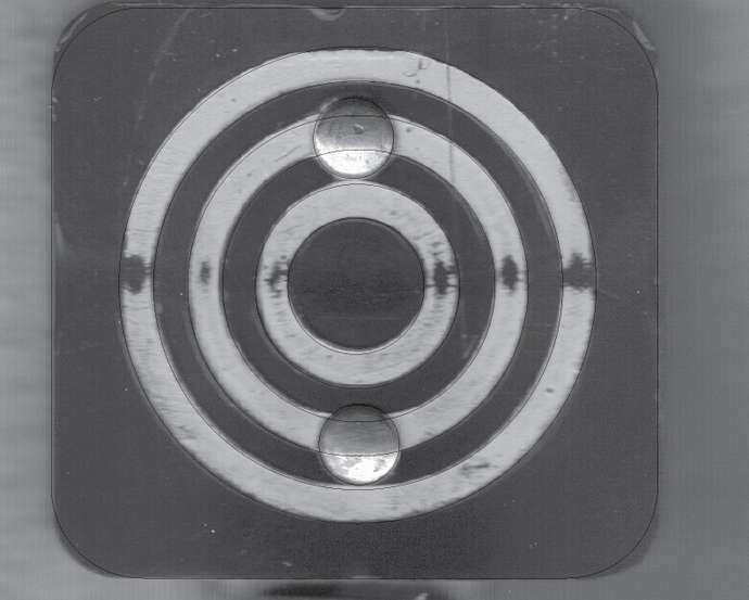
| + | If working with an existing part, use a scanner to get a 1:1 image of the item to allow for vector tracing. Then bring the scan into a vector editor like '''Illustrator''' or '''Inkscape''', and create the vector outline of where the cuts should be made for the stencil. | ||
| + | |||
| + | [[Image:stencil-cut-1.jpg|300px]] | ||
| + | |||
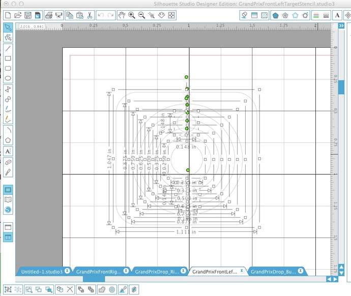
| + | Once the vector is complete, the drawing can be imported into the ''Silhouette'' software bundled with the cutter to create a cut plot. | ||
| + | |||
| + | [[Image:stencil-cut-2.jpg|300px]] | ||
| + | |||
| + | At that point, the stencil can be cut and weeded. | ||
| + | |||
| + | [[Image:stencil-cut-3.jpg|300px]] | ||
| + | |||
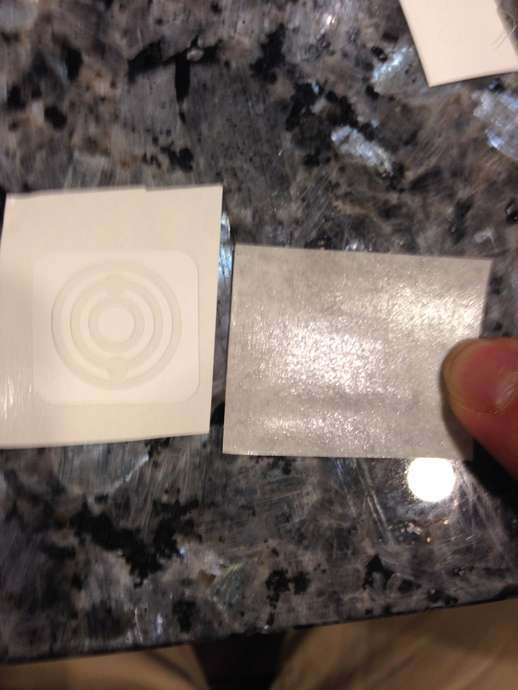
| + | Apply the transfer tape to the stencil material, which allows it to be peeled off the backing and then applied to the surface to be painted. | ||
| + | |||
| + | [[Image:stencil-cut-4.jpg|300px]] | ||
| + | |||
| + | Pull the transfer tape off, leaving the stencil in place. | ||
| + | |||
| + | [[Image:stencil-cut-5.jpg|300px]] | ||
| + | |||
| + | At this point the part can be painted. Once the stencil is removed, the finished part is ready for installation. | ||
| + | |||
| + | [[Image:stencil-cut-6.jpg|300px]] | ||
| + | |||
| + | === Ball Guides === | ||
| + | |||
| + | Ball guides can be made from 18ga or 16ga stainless steel. Older Gottlieb guides were measured at 18ga, whereas some newer guides are 16ga. Heights for ball guides are typically no shorter than 1-1/8" (28.575mm). | ||
| + | |||
| + | You can buy some pre-cut guides from [https://mantispinball.com/product/misc-ball-guide-kit/ Mantis Amusements], '''Stainless 304''' cut to size from [http://www.onlinemetals.com/merchant.cfm?pid=717&step=4&showunits=inches&id=30&top_cat=1 Online Metals] and '''Stainless 316''' strip from [https://www.mcmaster.com/#9090k1/=16kggof McMaster-Carr]. | ||
Latest revision as of 02:28, 19 February 2024
Contents
Tools
Specialty Tools
- Pop Bumper Drilling Template: For use when drilling the playfield for Williams-style pop bumpers. Instructions for use here. *pinbits appears to be out of business
- Dupont KF2510 Crimper: Usually priced under $20 on ebay, this connector crimper works incredibly well. Used with 100 mil spaced connectors, standard pinball molex connectors, and spade terminals. It has three different sizes for different connectors. The trick is to start the crimp so that the ratchet holds the connector in its teeth. Slip the wire in to the terminal, and then finish crushing the crimp. The crimps are nice and tight and hold the wires very securely.
- Amazon has tubular Riveting tools and supplies from Hanson Rivet Supply. These rivets are typically used to attach plastics to metals in pinball machines. Example: Ramp flaps to Ramps. Lamp Sockets to Plastics. more detail
Metalworking Tools
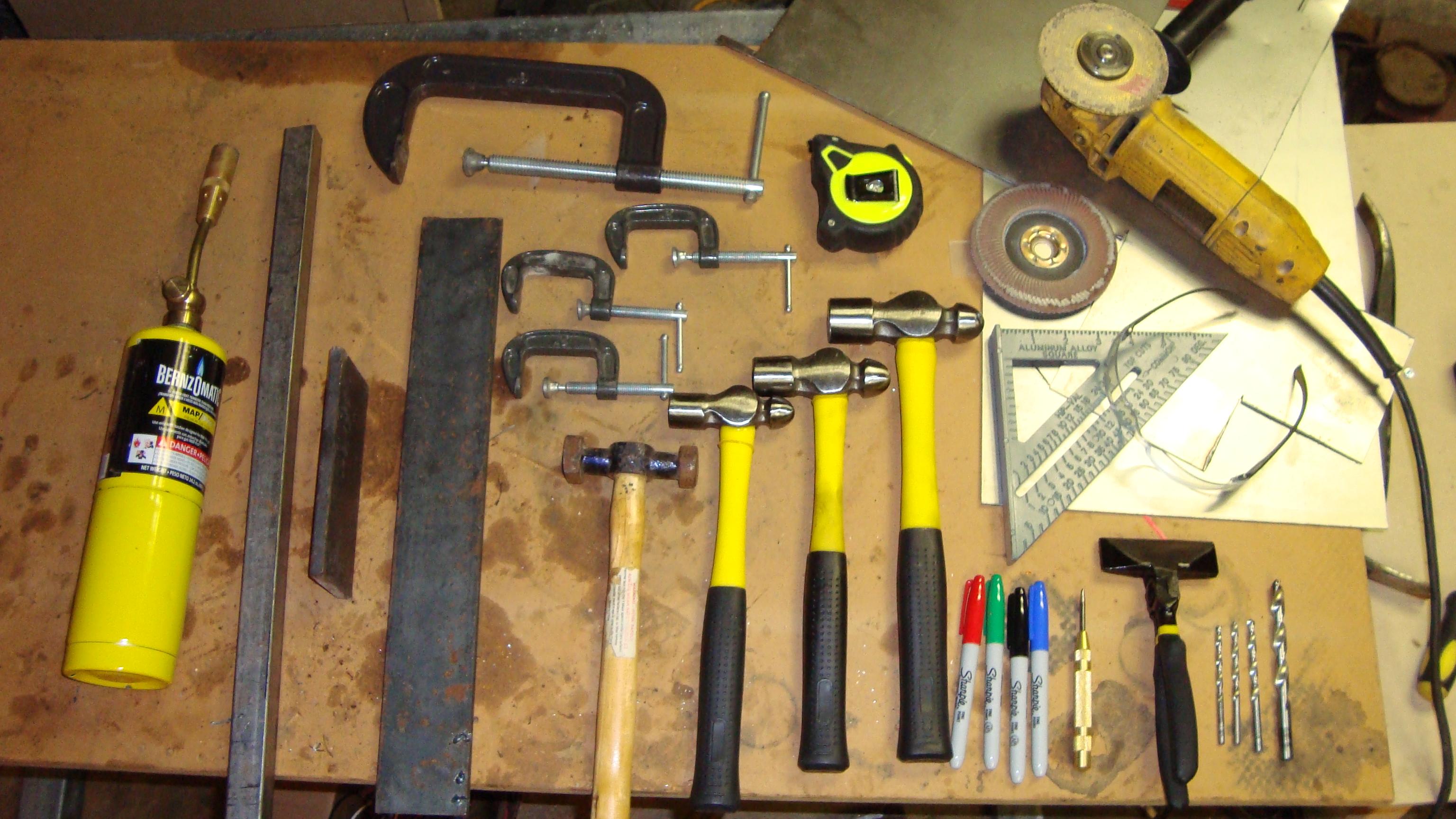
- A few different colored sharpies for marking cuts and bends
- 4 1/2" angle grinder for cutting and grinding
- Flap disc grinding pads of multiple grits
- Metal cutting blades for a grinder
- Safety glasses and gloves
- A bunch of different size C-clamps - at least one large and two big enough to clamp large items
- A Square
- Measuring tape
- Different sized ballpein hammers
- Drill bits for steel
- Center punch
- Blow Torch - MAP Gas works best, Propane as a second choice
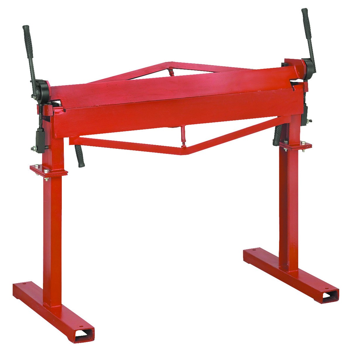
A Metal Brake is useful for bending sheet steel to make brackets.
The above example is available from Harbor Freight.
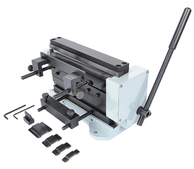
If space is at a premium, there are smaller tabletop versions as well.
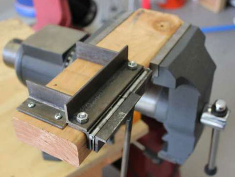
If cost is an issue, you can make your own from common hardware store parts.
Woodworking Tools
Beyond the standard hand tools needed to create a machine from scratch, here are some additional tools:
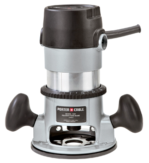
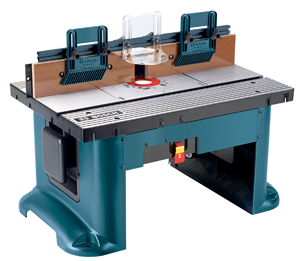
A Hand Router for creating insert and device holes in the playfield.
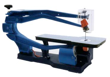
A Table Jigsaw for cutting playfield plastics, or plexi for your initial whitewood inserts.
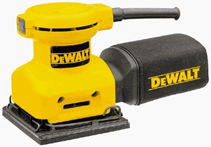
A Hand Sander to level the playfield. You should also have sand paper in various grits ranging from 180 up to 320, plus finer grits for final polishing.
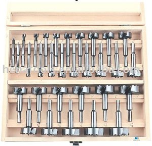
Forstner bits for drilling clean holes. Easier than using the router.
Cabinet Tools
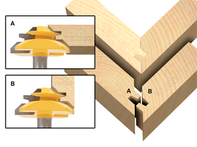
For cabinet building, a table router with Locking Mitre bits.
It is a bit that creates a locking edge between cabinet corners.
Rotisserie
While not a necessity, it makes populating a playfield much easier (both top and the bottom wiring and mechanics). This is true both of shopping an existing pin, and creating one from scratch. It's purpose is to hold the playfield securely, but still allowing it to be rotated 360 degrees (to flip back and forth between top and bottom surface). It also makes touching up playfield art easier and can prevent back pain by not having to crouch over a pinball cabinet.
It is also possible to test play a layout while mounted to a rotisserie, so long as it has been leveled and there are rails around the perimeter to keep the ball from falling off. Sometimes the cabinet walls are used as walls for the playfield. Flipper buttons will also need to be temporarily wired up to actuate the flippers, and a bracket to mount a plunger if testing skill shots.
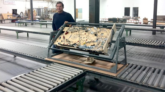
Factories will often fabricate elaborate and sturdy rotisseries out of thick steel since they may be used thousands of times per year:
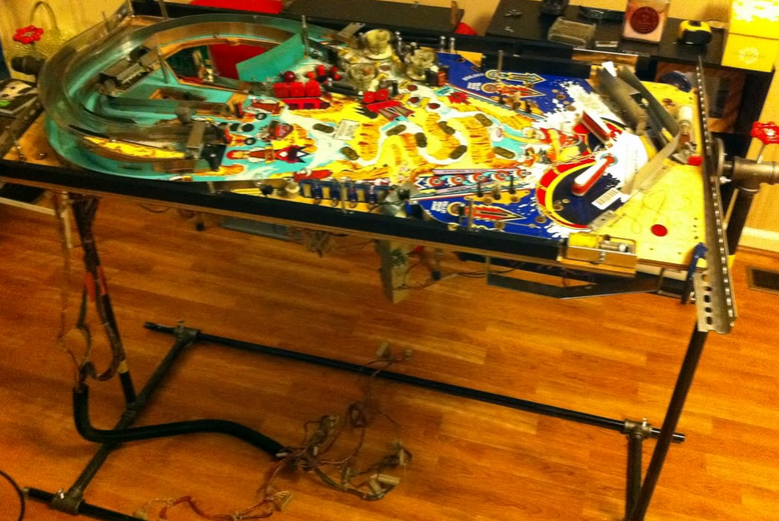
A hobbyist rotisserie doesn't need to be this elaborate. The most common rotisserie plan available online uses black gas pipes as the base, an angle plate for the playfield to rest on, and C-clamps to keep the playfield mounted:
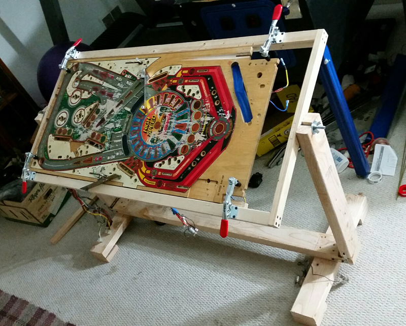
This design is functional but not without flaws. It costs upwards of $50 in supplies, the clamps most use can mark the playfield if not careful, and it can sometimes be difficult to get it set up. An alternate is to build it out of wood (reducing the chances of scratching the playfield when mounted), and using toggle clamps with rubber tips to protect the playfield:
Advanced Tools
Although not strictly needed for hobbyists, the following are nice-to-have if you have some deep pockets, and they make whitewood production much faster and far more consistent. Rather than purchasing these, the best option is to find a local Maker Space that has the equipment available for rent or through a monthly membership.
CNC
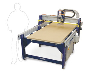
A large-format CNC machine can take drawings from AutoCAD or Inkscape to cut a playfield exactly to the design, which will be much more accurate than one done by hand with a router.
Some reasonably-priced options include:
For smaller parts, there are much cheaper alternatives:
- Shapeoko uses a standard hand router, like a Dremel, as the cutting tool, and is priced under $1K.
Laser Cutters
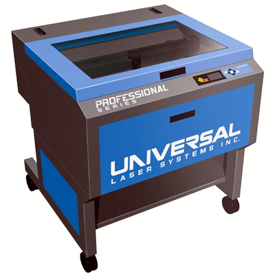
Using a laser cutter on plastics means fast prototyping of playfield plastics, and most cutters will also do engraving for interesting effects. Really high powered units will cut wood as well.
Some examples include Epilog and Universal.
A lower cost option is the Full Spectrum Laser.
Materials
A rundown of the various materials needed to produce a whitewood.
Plywood
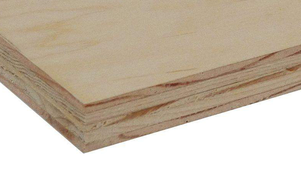
Commercial pinball machines use a specially sourced plywood that is not available from big box stores and generally not even specialty wood suppliers. Baltic Birch plywood has many more plys than big box store plywood. All the layers are Birch, so it is a very hard, heavy plywood.
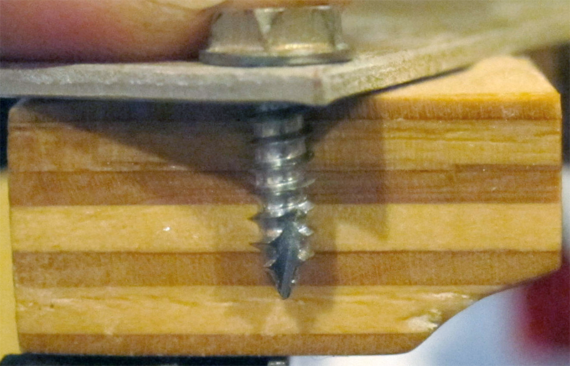
The type of plywood available at a big box store will have a thin ply on both sides, generally of softer Baltic Birch, and will not have the surface area to allow a full 1/32" sanding to level the surface and inserts together. It will also have large voids inside.
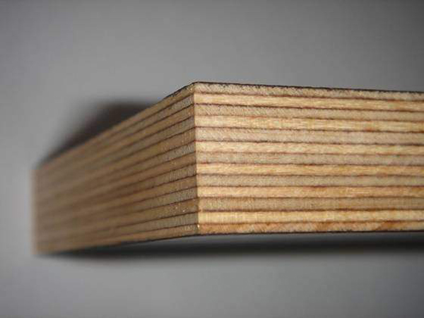
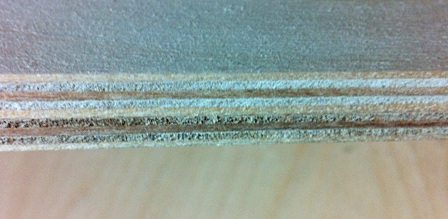
The thickness of a raw playfield is 17/32", which is then sanded on top with inserts installed to a finished size of 1/2". Each side is a full face of hard Birch with five plys in-between, not a thin veneer to allow for this sanding. The following photo illustrates the full seven plys:
For hobbyists, the best option is Cabinet Grade plywood, preferably from a lumber yard, with a minimum of seven plys but a preference for nine - the more plys, the more stable and flat. This type of plywood will have a thicker top and bottom ply suitable for sanding. It will generally be the softer maple but for one-off games, it should prove acceptable.
Another affordable option for whitewoods is Medium Density Fibreboard. Typically sold as MDF, it is also available in large quantities. The drawback for MDF is that it has poor flexibility and does not allow for easy removal and re-installation of screwed in parts. It is also a very heavy material since it is so dense. It is highly recommended to avoid using MDF for final playfields.
Sheetmetal
For ramps, ball guides and various other uses.
Sheet Steel at McMaster-Carr.
Sheet Steel including stainless at Grainger.
Inserts
For a whitewood, the easiest option is to use thin plexiglass for inserts as it is readily available and fairly easy to cut to size with a table jigsaw. This allows for skipping the final sanding stage if using 1/2" plywood instead of 17/32".
Real pinball inserts are available in various sizes and colors from a number of suppliers including Pinball Resource and Marco Specialities.
Some examples of the inserts available:
5/8″ round White opaque #PI-58RW
1-1/2″ triangle Green #PI-112TGT
Rollover star button housing red 3A-7537 #C-901
Standard depth of inserts are 1/4" and they are designed to be sanded flat after installation - there will be a number cast into the top of the part and the top edge will be slightly raised around the radius by approximately 1/32". Thus, when creating insert holes, you must drill slightly less than 1/4" deep to allow for the sanding.
Playfield Parts
The best source of parts like switch targets, pop bumpers, posts and other miscellaneous bits is from parts machines - picking up a used machine with a worn playfield and just cleaning up those parts will be ten times cheaper than buying all new parts.
However, given the increasing value of even older solid-state machines, finding games to part out is becoming increasingly difficult, so the only option may be purchasing new.
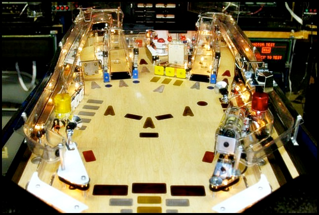
Once a preliminary design is complete, the next step is to create an initial prototype, known in the industry as a Whitewood.
Thankfully there are a number of standard devices that appear on modern machines that can be used on custom games, saving the garage maker a lot of time and effort by providing ready-made parts that don't need to be made from scratch.
Most of these basics are available from Pinball Life in the "Homebrew" section.
Microswitches
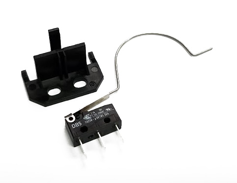
The majority of switches in a game will consist of ones mounted under the playfield with a wire sticking up above that the ball will roll over to activate. Older games used leaf switches but modern one will use microswitches. These can be wired directly into your switch inputs and are normally open in that they make an electrical connection when the switch is activated.
Opto Switches
The following information was sourced from a blog post by Scott Danesi and used with permission.
The most common style of optos are the Bally/Williams WPC style opto transmitter and receiver, available as an assembly ready to use. The LED emitter has no circuitry attached to it by default.
In order to safely power this type of LED, you will need to know the forward voltage of the LED, the maximum constant current that the LED can handle, what input voltage to supply to it (5v or 12v), and how much current to give the LED to ensure it has enough power to transmit infrared light to reach the opposite opto receiver.
For the WPC style opto the values are:
- Forward Voltage: 1.7v
- Max Constant Current: 100mA, but it is recommended to not exceed 75mA to maximize the life of the LED. This will be powerful enough to transmit a decent amount of distance between the emitter and receiver.
- Input Source Voltage: 5v DC is recommended as it is higher than the forward voltage of the LED, and low enough that the resistor does not have to dissipate too much heat.
These LED emitters will need a current limiting resistor in series with them as applying 5v or 12v directly to the LED will cause it to overload and fail. Using a Resistance Calculator, the resistor value can be easily determined.
Important: Be sure to use at least the minimum recommended resistor wattage. The calculator above is recommending at least a 1/2 watt resistor. Too small of a resistor and it can burn up,
On the receiver end, it can simply be wired directly to the inputs of your switch board. It will behave just like a standard switch as long as it is connected in the correct orientation. The cathode (ground) side of the emitter is the side with the flat indentation on the black epoxy base. However, note that opto receivers are normally closed switches and when it detects the IR beam from the emitter, it will be in a closed state, which is the opposite of a normal switch. When a ball breaks the opto beam it will go from a closed state to an open state, so your software needs to understand this.
Ball Trough
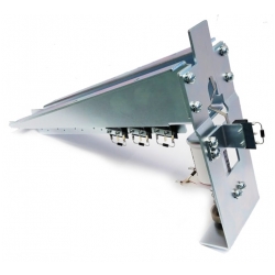
The trough is positioned at the bottom of the playfield and is used to collect all the balls used in standard game play. Originally holding only a single ball, it has evolved over the years and current versions can hold anywhere from one to six balls.
Here is an original Gottlieb single ball trough:
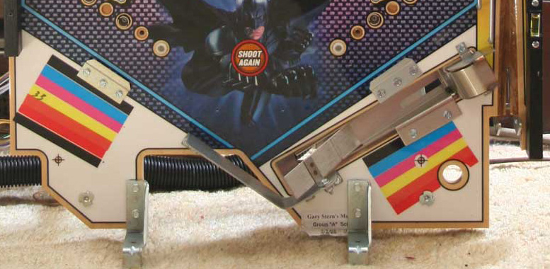
Here is an example of a Stern trough installed on a Batman playfield:
Pinball Life offers an affordable trough that will work well in custom applications. It's available in a 3-ball and 6-ball version.
Slingshots
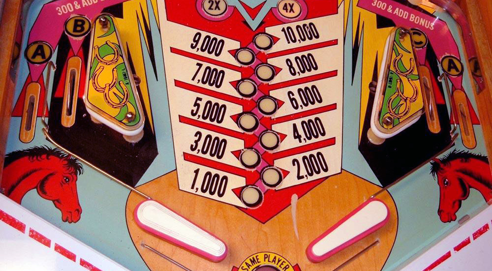
Slingshots are the objects above the flippers that kick the ball in the general direction of each other and towards the outlanes due to their upward angle. The lower playfield layout for modern machines has become a standard of two flippers, two outlanes, two inlanes, and two slingshots in a standard layout.
For example, here is a 1977 Gottlieb Mustang EM game illustrating the standard layout that has remained mostly unchanged in the last 30 years:
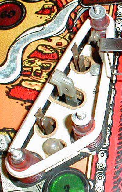
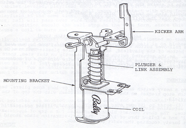
The mechanism for slightshots involves a coil under the playfield that fires when a ball hits the rubber ring of the slingshot, closes one of two switches to register the hit, then propelling the ball in the opposite direction.
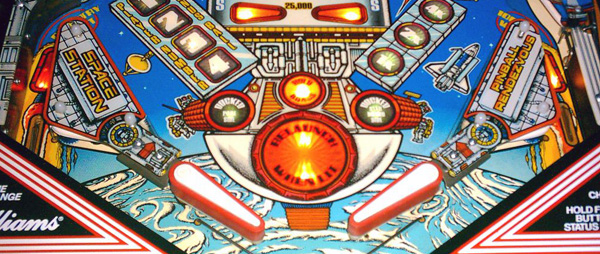
Configuration for slingshots is not limited to just the standard layout, so home builders are free to layout slingshots in whatever manner they like. Occasionally even manufacturers themselves deviate from the standard layout - for example, Williams Space Station has no inlanes:
Drop Targets
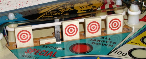
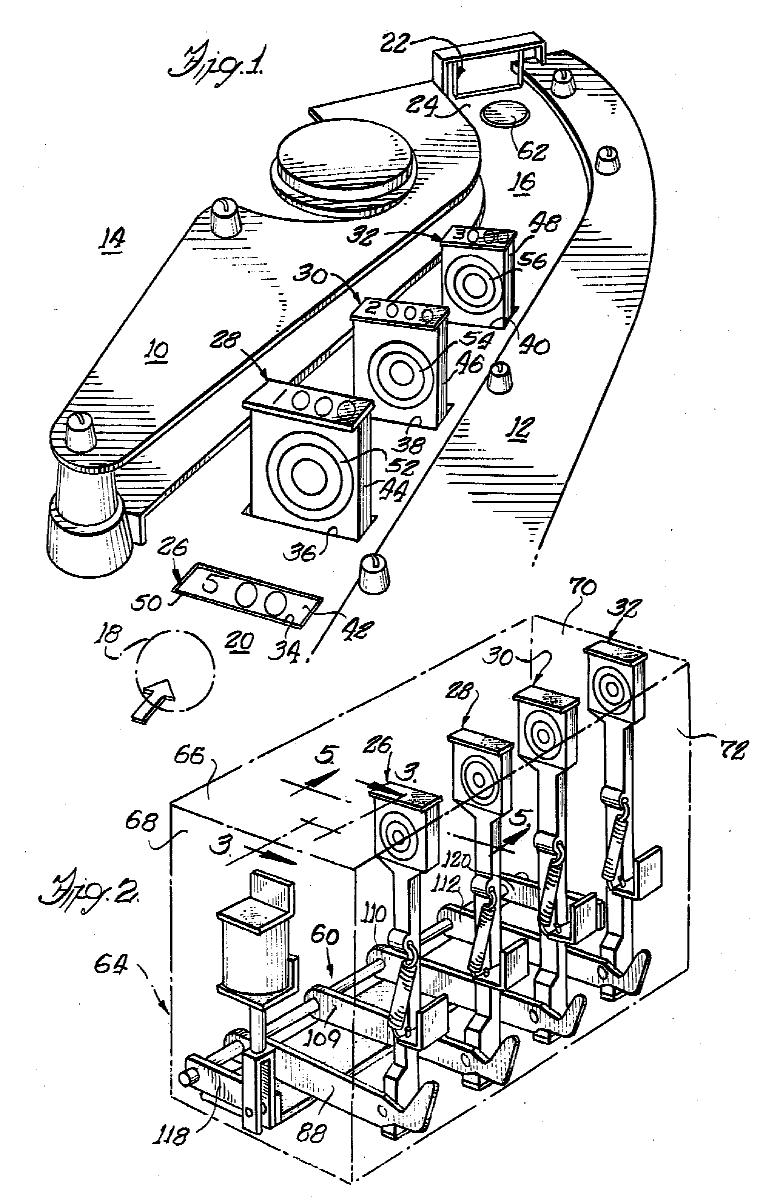
A Drop Target is a flat mechanical target that is held up on a small ledge and when hit with a ball, is moved backwards and dropped down via a small spring. There are generally switches for both the Up and Down positions but just a single Down switch will work. They can be arranged as single targets or in rows.
Every manufacturer has their own designs and use a variety of switch types to detect the target position - Williams used optos while modern Stern games use microswitches.
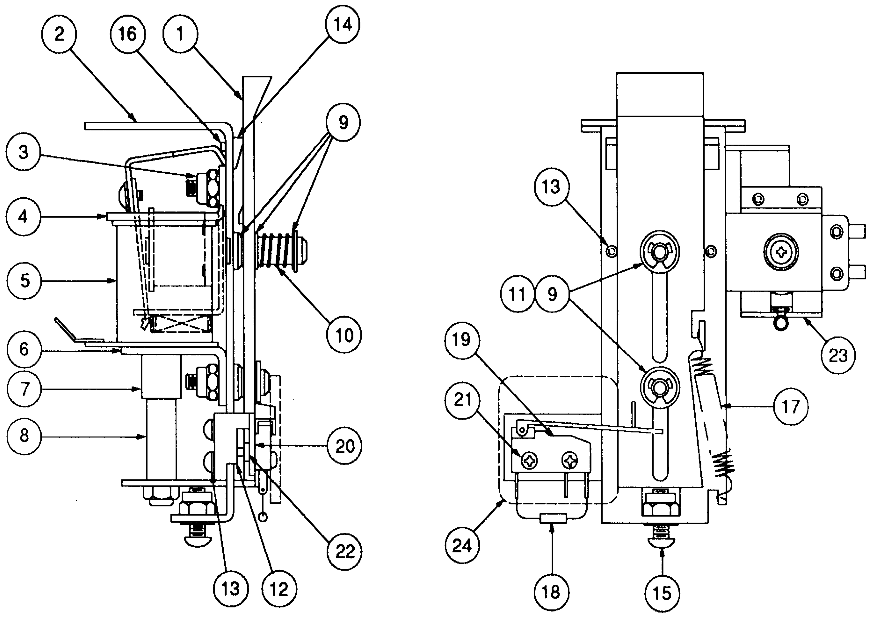
Diagram of a standard Williams target including a drop coil:
They are also available in an Inline format.
Drop Targets are available in many of the usual mail-order establishments such as Pinball Life but usually come in only the standard colors such as Opaque Red, Yellow, Black or White. If you are planning on Back-lighting the drop targets with LEDs for effect or mode selection; Pinball-Mods.com offers Drop Targets in Frosted "Clear" Polycarbonate for exactly this purpose. Make a custom stencil and you have a theme specific drop target.
Kickback
The kickback feature in a pinball machine allows the player to continue where they would have otherwise drained out of either outlane. A solenoid fires (not unlike an auto-plunger) against the ball, which quickly shoots it up the outlane and back into the playfield. For many games, this is enabled as part of the ball save and given to the player as a reward during normal play.
The solenoid is mounted in the apron area, and a lane guide will need to be mounted for the ball to properly shoot upward and out. Normally there is a playfield lamp in the outlane to indicate to the player kickback is active.
VUK
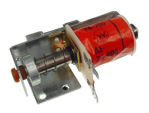
Also known as Vertical Up-Kicker, this is a scoop with a vertically mounted coil under the playfield with a plunger that kicks the ball vertically, typically through a scoop to bring a ball from one playfield to a higher one, or bring it up to wireform ramps. Scoop heights can vary, so there is really no stock part that will work in all applications.
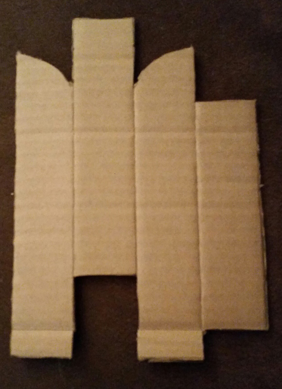
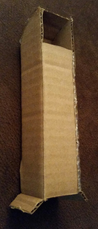
Below you can see a VUK scoop made from cardboard, first cut out as a flat sheet, then folded up and glued along the edges (similar to bending sheet metal and tacking the gaps). An even better material to use is Foam Core.
After the scoop has been tested thoroughly (as with any design), it can be transferred to sheet metal and welded, or bent from PETG plastic and glued. Be sure to include tabs for mounting to the playfield.
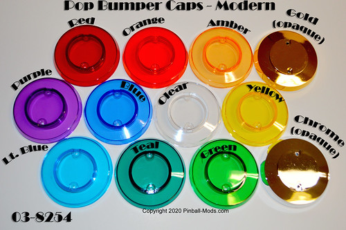
Pop Bumper Parts
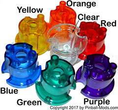
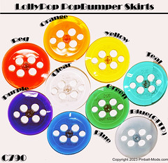
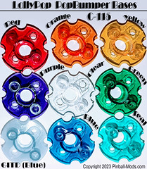
Retail Pop Bumper Bodies are starting to come in nearly every color of the rainbow so you can somewhat easily match to color of bodies to your artwork, pop caps, or intended lighting.
Modern Pop Bumper Parts
Pinball Life sells most standard colors in the opaque category and include Red, Blue, Orange, Yellow, and Black. Additionally PBL sells matching Skirts in those same colors with the addition of Green, Teal, and Purple.
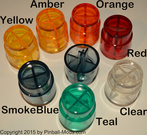
If you'd rather show art thru the pop bumper body, skirts, and bases; Pinball-Mods.com offers translucent modern popbodies, translucent skirts and bases; you can have artwork under the skirt for that little extra flair.
Try Pinball-Mods.com's Pop Bumper Configurator to make ordering simple.
Early SolidState Pop Bumper Parts
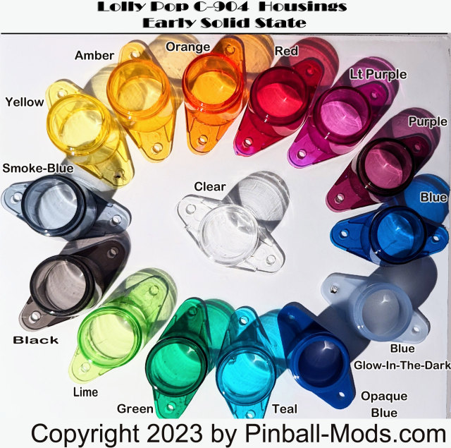
C-114 SolidState bodies are available early solid-state bodies in 9 different colors including Glow-In-The-Dark Blue. If you use their translucent skirts and bases; you can have artwork under the skirt for that little extra flair. Pinball-Mods.com offers both modern and early solid state Pop Bumper Caps.
Try Pinball-Mods.com's Pop Bumper Configurator to make ordering simple.
80s Bally Thumper Bumper Clip Style Parts
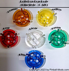
Available in opaque white from the usual vendors or in 6 translucent colors from Pinball-Mods.com C-970 Clip Body. The Clip Collars are available in the same colors along with the http://pinball-Mods.com/url/03-8277Cap?utm_source=pinballmakers PopCaps].
 [[Image:Clip03-8277Cap.jpg|240px]
Hangers
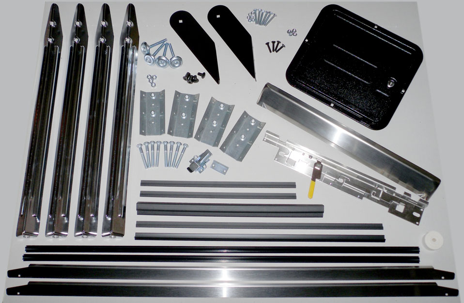
Hangers (sometimes spelled "hangars") are the brackets at the bottom of the playfield that attach to the lockdown bar mechanism to hold the playfield up. Every manufacturer seems to have slightly different styles. Early Williams used a Z-shaped bracket that installed from underneath the playfield.
The currently available off-the-shelf bracket is the Stern/Sega bracket that has a gusset shape, and are mounted above the playfield rather than below.
Switch Types
There are a number of options when selecting switches, all of which have been used in pinball machines over the years.
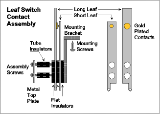
A Leaf switch consists of two metal blades held together in a contact assembly, with one of the blades generally being longer than the other. In a normally-open leaf switch, the longer blade is pushed toward the shorter blade to close the circuit. On a modern pinball machine, only normally-open switches are used.
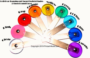
Translucent Colored switch blade targets are available at both Pinball.Center (for europe) and Pinball-Mods.com in North America. Available in 9 colors so they can be matched to any art style on your custom game.
A Microswitch is a small enclosed switch that has a sheet metal blade or wire actuator to operate the switch. The actuator is not electrically connected to the switch contacts, so it can be used in situations where directly moving one of the switch leaves would be dangerous. The blade or wire actuator can be bent into a convenient shape for the game requirements
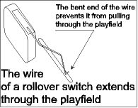
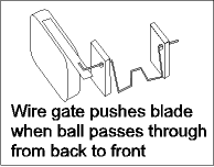
Microswitches with wire actuators are used for playfield roll-overs. The wire is bent to stick up through a slot in the playfield. When the ball rolls over the wire, it pushes down on the wire which operates the switch. Ones with blade actuators are used for detecting a ball passing through a gate. As the ball moves the wire gate, one end of the wire swivels down to press the blade which operates the switch.
Optical switches use an infra-red light emitting diode (LED) to activate a photo transistor. There are three variations that are useful in pinball machines:
- Slot-Type: A slot-type optical switch has the LED and the photo transistor mounted in the legs of a "U" shaped plastic. The light emitting diode is always on, and a "blade" that moves in and out of the slot interrupts the beam turning the photo transistor on and off.
- Reflective: An optical switch that has the LED and the photo transistor mounted side-by-side and facing outward. When a reflective surface comes near the switch, the beam from the LED reflects back to the photo transistor. Typical range for this type of switch is 3-6 millimeters or 1/8" to 1/4".
- Separates: An optical switch that has the LED and photo transistors in separate packages. The light emitting diode is always on, and an object moving between the LED and the photo transistor interrupts the beam turning the photo transistor on and off. The range for this type of switch can be up to 30 centimeters or 12".
Proximity switches may be inductive, ultrasonic, capacitive, or optical. A proximity switch detects the presence or absence of something within a certain proximity (or range) of the switch.
Inductive proximity switches work in two different ways. The Active type, an oscillator generates an electromagnetic field. When an electrically or magnetically conductive object enters the field of the oscillator, its frequency is altered, and the output switches. This type of switch can only be used when oscillator field will not sense too large an area. The Passive type uses a coil with an iron core or a semiconductor in a magnetic field (Hall effect sensor). A moving, magnetically conductive object disturbs the magnetic field and generates an electric current. This type of switch is not sensitive enough to detect a pinball reliably. It is used for detecting regular movement like gear wheel teeth rotating past, or with a magnet in a keyboard switch.
Capacitive proximity switches work in two different ways. The Passive type has a sensor that consists of two concentrically mounted electrodes (which are the electrodes of an opened capacitor). When an object approaches the sensor, the electrostatic field is changed. (It changes in opposite directions for conductive and non-conductive materials.) This change is detected by the switch. The Active type capacitive switches operate by generating a radio frequency. As an object approaches, the impedance seen by the radio frequency changes. This influence is measured within the circuitry and compared with the reference point set by the sensitivity adjustment.
The key factor for a switch is that it electrically completes a circuit, so they can consist of any two conductive objects being connected - so, even the pinball itself can be used as a switch if it connect two wires together!
Whitewood
The origin of the term whitewood is related to the material of the playfield, which is traditionally White Maple. The first iteration of a game will not have any artwork or lighting as the purpose is to test the layout, flipper shots and the overall feel of the design to confirm it plays as expected.
The second iteration of the whitewood - generally a different playfield rather than the existing one re-cut - will include inserts, lighting and any ramps or playfield devices needed for the complete game. This version of the prototype is used to create the first iteration of the ruleset and special effects.
Here is an unpopulated whitewood for Cirqus Voltaire, which is a later iteration that does have inserts for lighting, but not yet having artwork.
Here is a populated whitewood for AC/DC, which does not have the later sub-playfield so is much earlier in the design process.
Typically a playfield is made of 9-ply birch plywood, 17/32" thick with the additional 1/32" allowing for the inserts to be sanded flush. A number of European manufacturers used plastic playfields, and some domestic companies experimented with them in the 1970's, but the vast majority use plywood.
Playfield Sizes
Here is a list of playfield sizes by various manufacturers;
| Company | Type | Style | Inches |
|---|---|---|---|
| Alvin G | SS | Standard | 20.25" x 42.00" |
| Alvin G | SS | Mystery Castle | 20.25" x 46.00" |
| Atari | SS | Widebody | 27.00" x 45.00" |
| Bally | EM | Standard | 20.25" x 41.00" |
| Bally | SS | Standard | 20.25" x 42.00" |
| Bally | SS | Widebody | 26.75" x 40.50" |
| Capcom | SS | Standard | 20.25" x 46.00" |
| Data East | SS | Standard | 20.25" x 46.00" |
| Data East | SS | Widebody | 25.00" x 51.75" |
| Game Plan | SS | Standard | 20.25" x 42.00" |
| Gottlieb | EM | Standard | 20.25" x 41.00" |
| Gottlieb | System 1 | Standard | 20.25" x 42.00" |
| Gottlieb | System 80 | Standard | 20.25" x 42.00" |
| Gottlieb | System 80 | Widebody | 23.75" x 46.50" |
| Gottlieb | System 80 | Circus (Extra Wide) | 26.75" x 46.50" |
| Gottlieb | System 3 | Standard | 20.25" x 46.00" |
| Stern Electronics | SS | Standard | 20.25" x 42.00" |
| Stern Electronics | SS | Widebody | 23.875" x 45.00" |
| Stern Pinball | SS | Standard | 20.25" x 45.00" |
| Williams | System 1-11 | Standard | 20.25" x 42.00" |
| Williams | System 1-11 | Widebody | 27.00" x 42.00" |
| WMS | WPC | Safecracker | 16.50" x 41.50" |
| WMS | WPC (through 1987) | Standard | 20.50" x 42.00" |
| WMS | WPC (1987 on) | Standard | 20.25" x 44.5" |
| WMS | WPC | Superpin (Widebody) | 23.00" x 46.00" |
| WMS | Pinball 2000 | Standard | 20.50" x 43.00" |
| Zaccaria | SS | Standard | 20.25" x 42.00" |
Foam Core
When creating an initial whitewood to test shots, install the lower third (flippers, slingshots) and side rails, but use Foam Core for your ramps and any upper playfield stuff. It is easy to cut and form with hot glue, quickly and cleanly. It is also strong enough to endure test playing without breaking.
Use 1/4" to 1/8" for ramp bottoms, and hot glue thinner posterboard on the sides. You can also use posterboard for the transitions between the playfield and the ramps. Trace the shape of the ramp on the foam core, cut it out, then glue on thinner sides.
Foam core can also be used for stand ups, pop bumpers and other devices to test other shots. Either stack it or stand it up and glue it together. Use hot glue for everything - easy to use, dries quickly, holds strong, and you can rip it apart to change things as needed.
When complete, the game should be basically playable in terms of playfield and ramp shots, and if the game plays okay with foam core, it will play even better in plastic and metal.
An alternate to foam core (which can be pricey at $7 for a 2' x 3' sheet), is cardboard. It is a material that is readily available in multiple thicknesses and footprint sizes, often obtainable for free since it's such a highly recycled material. It can be bent at angles and remain stiff in fluted versions, or bent in a curve by squishing the flutes down, very similarly to sheet metal. Since cardboard has no foam inside, it can often be stiffer and closer to a harder material like plastic. It is as easily cut with an x-acto blade or scissors.
Cutting
(Sourced from a tutorial by Josh Kugler) [1]
Before proceeding with any cutting, a completed playfield drawing is needed, to be used as a template. For details on that portion of the process, visit the Design section of the wiki. One tip that will help later is to add centering lines to all the drilled insert circles to aid in proper placement.
Once complete, take the file to a FedexOffice or similar Printing House and have it printed full size. Use 3M Spray adhesive to glue the print to your playfield surface. This print acts as your drilling and cutting template.
Use two Forstner bits for each insert. The first is the wider opening that is the same size as the insert, drilled to the appropriate depth of the insert which is typically 1/4". The second bit is 1/16" smaller can then be used to drill the through hole. This leaves a 1/32" lip for the insert to sit on.
Since the Forstner bit has a centering point there is a natural centering hole for the second bit, making it easier to get it lined up right. The cleanest technique is to drill just short of going through, and then complete the hole from the other side using a standard cordless drill.
Don’t do the three steps in order per hole, but the first step for a bunch of holes, then the second and third.
For creating a non-circular insert, use a router with a template and Bushing guide - a router bit with a small roller bearing on it runs along your guide, while the cutting head runs in the playfield to cut the hole to the size of the template. Creating the template is the hard part, but once you have that, it is relatively easy to route multiple holes for the inserts. This is a three step process similar to the circular inserts.
As with the circular inserts, first create the wider opening. This is done by clamping the template to the playfield and then routing the wider opening using the bearing bit.
Drill a couple of holes in the center of the insert so there is less to route. This is also helpful when doing the second step, of cutting out the inner opening, that is slightly smaller then the insert opening, since the router bit can start in one of the holes and not have to be plunged into the wood.
A 3/16" bit and a 5/16" bushing/guide offers the best results, which gives a lip of 1/16", a little bigger then for the circular inserts. This second routing can be done without a template, since the insert opening itself can act as the template.
Cabinet
Made from 3/4" plywood, mitre-jointed at the corners. Some of the considerations when designing or building a pinball cabinet include:
- Switch locations
- Side rails
- Lockdown bar mechanism
- Plunger height
- Coindoor size
- Leg mounting brackets
- Speaker bezel
There are typically two cabinet styles, Standard body and Wide body.
Cabinet Parts
If building a Williams style standard cabinet, VirtuaPin offers a Ultimate Cab-Builder's Kit that has all the cabinet-specific parts in one handy kit.
Alternatively, for just the playfield mounting parts:
- 2x Stern Playfield Pivot Bracket 500-5329-03
- 2x Stern Edge Slide Bracket
- 1x Stern Slide & Pivot Support Bracket - Right
- 1x Stern Slide & Pivot Support Bracket - Left
- 2x Stern Playfield Hanger Bracket
- 1x WMS Lockdown Bar Lever Guide Receiver Assembly
- 1x WMS Standard Size Stainless Steel Lockdown Bar
When cutting your cabinet for the coin door, keep in mind it is installed with four bolts centered on the bottom, sides and top, and that the top hole goes through the lockdown bracket. So both need to line up.
Off-the-shell Cabinet Parts
Custom pinball machine cabinets is becoming easier due to many vendors providing "mod" friendly cabinet parts.
Flipper Buttons
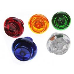 Pinball-Life sells both opaque and translucent modern flipper buttons compatible with Stern and late model Williams cabinets.
Pinball-Mods.com offers both the Buttons and Housings for early solid state machine cabinets by Bally, Gottlieb, Stern, and Chicago Coin which can be lit with LEDs using a technique documented in a Pinside thread.
Electronics
Once the physical playfield is constructed, wiring it all together and adding a way to control the devices will be required. There are three basic options - use existing pinball boards, build custom control boards or purchase off-the-shelf units.
Existing Boards
A popular option is using boards from existing machines and replacing the main controller. For example, the Gottlieb System 3 driver board uses modern MOSFET drivers, supports 32 coils and a 8x10 lamp matrix, and is available for $100 from Pinball Resource.
Another well documented system is the original Bally system.
Custom Boards
- Open Pinball Project is a low-cost, DIY solution for basic pinball control and is a good way to learn pinball control systems. There is extensive documentation hosted on this wiki.
- Pinheck is a system designed by Ben Heck for use in America's Most Haunted and is not currently available in kit form, but you can download the design and have it printed yourself for use in your own games.
- System Shock is a work-in-progress and currently only the driver board is available for download.
Off-the-Shelf Boards
- P-ROC (Pinball - Remote Operations Controller) is a well-supported generic platform that is in use by many custom games. It has a dedicated forum.
- FAST Pinball has controllers and board comparable to P-ROC.
- CobraPin Pinball Controller Is a fully assembled control solution based on the infrastructure of OPP.
Controller PCs
Most off-the-shelf systems require an external PC with USB to provide the signals to control the solenoids and lamps. Currently these small ARM-based boards are the best candidates as they are more powerful than the Raspberry Pi or Arduino boards:
- O-DROID : Quad-core CPU, dual-core GPU, 1GB DDR3 RAM, Gigabit Ethernet , 4x USB2.0 ports.
- Beaglebone Black: AM335x 1GHz ARM® Cortex-A8, 512MB DDR3 RAM, 4GB 8-bit eMMC on-board flash storage
- CubieTruck: ARM® Cortex™-A7 Dual-Core, 2GB DDR3, HDMI & VGA 1080P display output, 10M/100M/1G Ethernet, Wifi + BT, SATA 2.0 , NAND+MicroSD or TSD+ MicroSD or 2*MicroSD
Coil Sizes
When choosing coils, it is important to understand how coil sizing works.
For example, decoding the Williams part number AL-23-550 has three parts - the prefix AL means the coil has base wire lugs on the left and middle of the coil's base, while 23 is 23 gauge wire and 550 is the number of turns of wire. The more turns, the weaker the coil.
For more details on coils, check out the Pinball Medic coil chart.
Power Supplies
There are a couple of options when it comes to power.
- Commercial Pinball Transformer / Power Supply: Most dedicated pinball transformers will provide various power level taps like 6.3V for the GI and CPU, 24V for basic coils and 50V for flippers and other high-current coils. You'll need the comparable power supply board to convert the AC voltages to DC, or create the power supply yourself.
- AnTek: The model PS-4N70R5R12 provides high current 70V as well as 1A 5V/12V feeds to run the CPU and lights.
- TDK-Lamda: Available from Digikey. Model LS150-36 is a 36V switching supply, suitable for most standard coils but may not be enough for flippers or VUKs.
- Meanwell: The SE-600-48 is a 48V 12A supply which can be dialed up to 50v. There are also lower amperage 48V models such as the Meanwell NES-350-48 which provides 7A. Meanwell is a highly respected brand that make very good power supplies.
- eBay: Search for CNC Power Supplies. These will often be 48V high current switching supplies designed for stepper motors and will provide enough power for coils so long as the maximum current isn't exceeded.
Selecting Power Supplies
It is recommended to get at least a 3A supply for coils. The quality, especially from China, is not always guaranteed. Be sure to choose one with a case that has adequate venting to prevent shorts if any metal items are dropped on the circuitry. Power supplies with fans are recommended. They typically won't turn on unless they get hot enough (Coils pulling excessive current, hot ambient temperature). Sometimes coils may pull more amps than the power supply can provide, so wiring in resistors and capacitors (to buffer energy) may be necessary so the power supply doesn't reset.
Computer power supplies are fine for CPU and some lighting, but won't provide enough current for solenoids. If using a standard PC as the CPU for the machine, there is a useful board for controlling PC power supplies from the external high-current supply.
With modern switching power supplies, having one supply for coils and another for CPU / LEDs is common, so please remember that All grounds from all supplies need to be connected together otherwise it may create a floating ground situation that can lead to destroying boards and other electronics.
Capacitor / Filter Board
Using a modern switcher with coils means using a Capacitor Board between the supply and any solenoids to provide coils that sudden onrush of current. Some options include:
The Multimorphic Power Entry PCB distributes AC power and up to 4 different DC voltages, generally 5v, 12v, 15v, and “high voltage” (typically 48v or 70v). A 12v relay enables the “high voltage” output. LEDs identify the presence of each of the 4 DC voltages.
The FAST Power Filter Board provides capacitor filtering and fusing.
For those interested in DIY solutions, the OPP Power Filter Board provides similar functionality.
Wiring
Most pinball machines have wire harnesses of some type. As high-current devices, solenoids typically need a minimum of 18AWG wire. Wiring for lighting and switches can be much thinner since it's pulling less current, particularly if using LEDs, so 20-22AWG wiring is acceptable for low-current uses.
Connectors
Most Pinball machines use the Molex KK Series connectors in the 0.100" and 0.156" sizes. There is a PDF with the part numbers from Mouser in the Files section.
Wire Management
Because prototyping (or one-off) projects don't have pre-determined wire lengths and quantities, how wire is routed will change many times before the game is complete. It is highly recommended to use tie mount bases (with adhesive) versus clips that are permanently screwed into the playfield. That way they can be moved around as needed.
It is also recommended to use re-usable tie-wraps, which allow repeated opening and closing as needed.
Here is an example of a prototype playfield using these types of wire holders:
Wiring Harness
Once the final wiring layout is complete, paper templates of the playfield layout on thick cardboard or wood paneling can be used to make a Wiring Pinboard, similar to the boards that the manufacturers use to make their Wiring Harnesses. Place nails in appropriate spots and run wires as needed, with tie-wraps.
Color Coding
To aid in troubleshooting and wire layout, pinball companies use color-coded wire, where it has one color as the main jacket and a second color as a smaller stripe, allowing for many color combinations. For instance, Williams used yellow and white wire for lamps.
Getting a full stock color-coded wire can be very expensive, but the folks at Mission Pinball came up with a cheaper alternative method of properly color-coding wire using cheap PVC piping.
Start with purchasing single-color wire in 50' - 100' spools. Get 18 and 20AWG spools for each type of wiring. The more base colors to start, the better.
Next, get some oil-based markers, which can be found at local hobby stores. One notable brand is Sharpie, and they should be labeled specifically as oil-based paint markers - water-based will scratch or wipe off easily. They will be more expensive but are the only type that work correctly.
Although Mission used a wood block to hold the markers, using a PVC T joint and drilling a hole through it in the center allows the placement of the paint marker in the T portion of the joint and pressing down on the wire as it passes through works very well.
Matrix Color Coding
Where color-coding is particularly important is in Switch and Lamp Matrix layouts. Plan ahead and design your color scheme before starting the construction of the game in a spreadsheet.
Below is an example of a color layout for a custom game. This document can be referenced during construction to make sure the right wire is going to the right switch, lamp or coil, avoiding troublesome issues later during the testing phase.
Displays
Numeric / Alphanumeric
Numeric or Alphanumeric score displays are sometimes chosen even today because of the ease of programming - they display simple scores or lines of text only, so no complicated graphics need to be designed or coded. That means more time to concentrate on gameplay versus interfacing with the player.
Gas Plasma
The first commercial solid-state displays in common usage were Gas Plasma displays. They use high voltage to cause a noble gas like neon to glow. Shaping the conductive layers into digits allows the display of multiple numbers or letters.
These types of displays are not only dangerous, due to the high voltages required, they are prone to burn-out or out-gassing, and have been obsolete for many years. Unless re-theming an older game and wanting to re-use existing parts, or trying to maintain a retro look, it is suggested to use LED replacements.
LED Displays
The pinball after-market has produced a number of excellent plug-and-play LED display replacements.
- X-PIN has 6- and 7-segment displays as well as alphanumerics.
- Pinscore has retrofit kits for older machines.
- PinLED in Europe has a variety of options available.
Additionally, there are many generic LED displays to choose from:
- Adafruit offers a number of LED segment displays with instructions on programming them with various microcontrollers.
Dot Matrix
Modern games make use of either a gas plasma or LED Dox Matrix Display or DMD. They work on the same principle as the segment display except they use round pixels in a grid pattern - or matrix - to display game information.
The complexity with these displays is that the programmer must construct numbers or letters in a graphic format and then push that data to the display. Rather than program "display 300,000", they must use bitmap fonts and determine screen placement.
However, many programming frameworks currently available offer this functionality built in and are an excellent place to start learning about game graphics.
Other options for matrix displays include:
- Evil Mad Scientist offers the Peggy 2 DMD kit for exploring DMD programming.
- Adafruit has a variety of matrix boards with programming instructions included.
- Embedded Adventures has kits as well.
LCD Display
The trend for modern games is using LCD screens in place of DMDs or other older display technologies. Full color with high resolution, the results can be very attractive. However, at this level a game designer essentially becomes a videogame designer. A pinball maker has to wear many hats but it is the rare individual who can do both construction and handle graphics duties.
There is some discussion of the technical side of graphical displays on the pinballcontrollers Forum.
Lighting
Pinball lighting comes in two varieties - incandescent and LED. Older incandescent games can be retrofitted with modern LED lamps, or when fully customizing, replaced with custom board-mounted LEDs or Serial Chain LEDs.
Socket Styles
For incandescent, most lighting is socketed either by a bayonet or wedge socket.
Bayonet is preferred since the bulb is more likely not to wiggle itself out from vibration during play and transport. While pinball started out with incandescent bulbs, most are moving towards LED for many reasons:
- Less power draw
- More color options
- Lasts longer which means replacing less often
- Less damaging. The constant heat/cool from incandescent bulbs are known to warp plastics and cause flaking on backglasses.
Recently; Pinball.Center and Pinball-Mods.com began offering Lollypop wedge bases for use on Ramps and other Plastics. Offered in 7 modder friendly colors.
Bulb Mount Types
The most common sizes are the #44/#47 Bayonet Base, the #555 Wedge Base, the #89 Bayonet and the #906 Wedge.
One drawback of LED's are that they don't have a ramp-up of brightness like incandescent bulbs, and sometimes they can be bright enough to hurt the eyes. The ramp-up effect can be emulated in software if the lamp controller has enough brightness levels, and diffusion-style bulbs help the brightness issue. They are best used as General Illumination.
Modern Stern games going forward use a Surface Mount LED board that are driven directly which eliminates the need for sockets altogether. The drawback to these are that the boards are directly soldered, so if there are issues, they can't be easily replaced. However, the long life of LEDs makes it unlikely for them to burn out at the rate incandescent lamps do.
For a custom game, a combination of Cointaker Premium Frosted or Ablaze 4-LED for GI and the FAST Pinball RGB LED Insert or Multimorphic RGB LED boards for inserts are a good choice.
Custom LED Boards
Many vendors provide custom lighting solutions which might not fit in a traditional socket as above or have specific pinball specific uses.
One example is the BriteCaps EVO mod for #555 Pop bumpers. These PCBs plug into the #555 socket typically found in most modern pop bumper assemblies.
Pinball Mods offers a Star Rollover LED which shines 4 LEDs from the underside of a star rollover and has a hole in the center to allow the switch actuator to function properly on the leaf switch.
For lighting translucent flipper buttons, a #44 socket and the Cointaker 44/47 Flex Super Bright lamps can be installed by attaching the socket under the flipper button and out of the way of the Flipper Button Leaf Switch. Comet Pinball also offers a light up kit for both modern and early solidstate flipper buttonswhich includes the buttons, wiring,m and leds.
Pinball Mods offers the Flipper Button Mod which displays a rotating 12 LED pattern behind early solid state Flipper buttons for project using the older style flipper buttons.
Custom Parts
Many hobbyists plan on producing games with game-specific features that aren't included in other machines, such as ramps or ball control devices, and thus will have to design and construct mechanisms from scratch. This generally involves metalworking, welding and other more advanced skills, but are not beyond the garage hobbyist.
Plastics
There will likely be many plastic shields scattered on the playfield to:
- Hide mechanisms
- Improve aesthetics
- Prevent a launched ball from getting stuck in a crevice
While using a laser cutter would be ideal, it is possible to produce plastics with basic hand tools. It is recommended to buy something easier to cut than acrylic, such as 1/16" PETG, which can be purchased from McMaster. This can be cut fairly easily with strong scissors (or an x-acto if used carefully), and like acrylic it can be flame polished.
To create artwork, the best method is to print it on photo paper, and then use a spray adhesive to attach it to the bottom of the plastic. Examples include 3M Super 77 (try to find the 25% lower VOC verison). These products dry clear and will not yellow.
Please use caution when using this product as it is extremely volatile!
First, trace the shape to be cut on the thin blue film on top of the plastic. Remove the film from the bottom where art is being applied. The artwork should be just slightly bigger than the plastic to ensure there are no gaps when trimmed.
Make sure to spray in light, even coats on the backside of the plastic. Let it get tacky for 10-15 seconds, then move the printed art (art side up) over, and turn the plastic over and apply the plastic onto the paper - this will make it easier to line it up.
This is what it will look like when first applied. The adhesive will turn clear as it dries.
Once the adhesive has dried, the holes can be drilled starting with a small bit, and working up to the hole size needed.
Trim off the excess paper by using the plastic as a guide. Trim slow and carefully as to not dig into the plastic with the knife.
Here's an example of prototyped plastics installed on the slingshots:
The white paper acts as a nice diffuser to spread the light out, just like the white ink layer on screenprinted plastics.
3D Printing
(From Wolfmarsh's Pinside tutorial)
The big revolution in garage building is 3D printing.
The most popular among home machines is Fused Deposition Modeling (FDM for short). FDM is where a thermoplastic filament is slightly melted, extruded through a small nozzle, and deposited in layers to build up the object. Most home printers use this method.
Here is an image that gives the general idea. One is the Extruder, two is the deposited Layers, and three is the Build platform.
A second method that is popular with the higher end machines, is Selective Laser Sintering (SLS). With SLS, a layer of powder is deposited on the build surface, then a laser melts specific areas together. The build surface lowers a fraction of a millimeter, and more powder is deposited. Repeat until the object is built. Here are a couple short videos that shows how SLS works:
https://www.youtube.com/watch?feature=player_embedded&v=sFpSxX0SzgY
https://www.youtube.com/watch?feature=player_embedded&v=-6ItiCbYFvI
Buying a Printer vs Using a Service
Most home printers will print using plastic filament and FDM. Services like Shapeways can afford higher end printers that offer higher resolution with SLS.
For most of what a garage builder will do, FDM and home printing will cover it. If a full color print or some very fine details are needed, like screw threads, the part can be ordered from Shapeways.
If planning to purchase a home printer, it is recommended to read the Make Guide to 3D printers. One option is the Printrbot Simple Metal Kit with a Heated Bed upgrade. There are many clones coming out now that patents have run out. If you look at the flashforge, there are 2-3 clones that are as cheap as half cost. Monoprice has a few options. While heated bed isn't necessary for PLA, heat does seem to help all materials and is necessary for ABS. Choice of materials will come down to nozzle temp, but you want one that can handle at least 230C or higher.
Generally with the lower cost kits, the only real sacrifice is speed and maximum build size.
Printing an Object
The easiest way to get into 3D printing without having to create models is to download pre-made models. A great source for this is Thingiverse. Pinball parts are starting to appear on Thingiverse, so there is a small library already available.
For example, here is a shooter lane designed by Pinside contributor swinks:
Download an .STL file of the model to print. It contains the geometry for the object in a language the printing software can understand. Once you have the .STL file, you feed it to a Slicing program like Slic3r. A slicing program takes a 3D model and cuts it into the layers needed to feed to the 3D printer.
Here is a quick example of how it works. The model is on the left, and the sliced version on the right.
Once the object has been sliced, the program will generate a G-code file, which is the common language that CNC machines use.
A G-code file looks like this:
G1 X52.008 Y54.121 E2.04455
G1 X51.948 Y52.484 E2.13013
G1 X51.969 Y52.373 E2.13608
G1 X52.042 Y50.606 E2.22844
G1 X52.067 Y50.514 E2.23342
G1 X52.258 Y48.934 E2.31658
G1 X52.708 Y48.561 E2.34712
G1 X52.998 Y48.608 E2.36247
G1 X54.421 Y48.632 E2.43686
G1 X54.532 Y48.659 E2.44282
This example is a bunch of G1 commands that tell the machine to move to a specific X position, a specific Y position, and to Extrude a specific amount of filament. The G-code file gets loaded into the Printer control software, and slowly fed to the printer as it prints the object.
The Printrbot example above can be driven using a Raspberry PI, running a special image called OctoPi. It provides a web interface to the printer.
If everything worked as expected, at the end of the print process there is a real, complete object based on the models:
If things don't go well, it may end up as a bunch of trash plastic. It happens.
The key is to experiment and find shapes that work well, and to design shapes with the properties of the materials being used - if building brackets to hold coils, the resulting bracket should be thick enough to maintain its shape when the coil fires. The following is an example from America's Most Haunted.
While all 3d printers should be monitored, once the first few layers stick it's generally safe for them to run un-monitored. PEI sheet beds help sticking, as do things like buildtak and zebra bed. This is much more convenient than replacing blue tape every build. As of this writing, there has never been a 3d printer reported to have thermal runaway and melt. Not to say electronics can't fail, but it's very unlikely. It's not uncommon for users to run batch print jobs overnight while they sleep. Some users have experimented with running jobs while not at home, but this usually requires both a webcam to monitor the print job, and a remote shutdown circuit that is internet enabled through a simple computer like arduino or a raspberry pi.
Software can make a big difference not only in build quality, but build support breakaway. Pay Programs like Simplify3d are not only superior in both of these, but it also spits out g-code very quickly. It also keeps updating with default printer settings as new printers come out. For free software, Cura seems to be the #1 choice.
Vacuum-Forming
(Sourced from a tutorial by Josh Kugler) [2]
Doing simple vacuum-forming in your garage is straight-forward. The basic idea is to use a standard oven to heat up a sheet of plastic until it softens, then place it over a pre-made form, using a vacuum to pull the plastic down around the form.
Materials needed to create the vacuum-former include:
- Wood Strips
- Pegboard (2' x 4')
- Plywood
- Shop Vac or similar
Sizes are not critical - the available space in the oven will determine the maximum final size of any pieces formed - so the unit should be built slightly larger than that.
Create a box using the wood strips and plywood, and caulk it to make it airtight.
Drill a hole the same size as the intake hose on your vacuum in the side or bottom of the box, and attach the pegboard to the top of the box. When you place your form on top of the box, then the heated plastic, the vacuum will draw the heated plastic down.
Using an old picture frame, or a cheap one from IKEA, trim your plastic sheet to the same size and heat the plastic in the frame in the oven at 375 degrees, until it just starts to droop. Placing the frame and plastic on oven-safe jars will prevent it from touching the racks or surface of the oven if it should droop too far.
In this photo, the extra airholes are blocked by poster board to maintain the airtight seal.
When creating forms, it is important to remember that it must be possible to cleanly remove the form once the process is complete, so things to avoid include:
- Large vertical surfaces
- Vertical holes
The best form is a pyramid shape, with the smallest details on top and increasing diameters to the base. Consider using a releasing agent to make removing the form easier - a non-stick spray or lubricant for example.
Creating the form itself can be done using foamcore, wood and bondo, aluminum or steel, depending on your available tools and ability. The smoother your initial form, the clearer your final pieces will be.
Welding
If you plan on making metal ramps or wireforms, welding will be required.
In order of quality, here are your welding options:
- TIG: Tungsten Inert Gas arc welding is often employed to make welds on nickel alloys (like stainless steel), magnesium, aluminum, titanium and copper alloys. TIG welds can be made with or without metal fillers, unlike MIG welding, which exclusively employs filler metals to create welds.
- Pros: Pinpoints heat better than MIG welding, allowing for smaller, more precise welding, is a very clean process, creating no spatter whatsoever while a weld is being made.
- Cons: TIG welders are more expensive than MIG welders, and it is a more difficult process to master.
- MIG: Metal Inert Gas arc welding is most often used with steel. MIG welders do not have to start and stop too often while welding, which allows for long, uninterrupted welds. Gas shields the weld, helping to prevent oxidation and spatter.
- Pros: Relatively clean, creating only a little spatter while welds are made, easier for beginners.
- Cons: Possibility of excessive melt-through and incomplete joint penetration or fusion, can be difficult to create a starting arc, welds are known to leave deposits that are heavily oxidized.
- Flux Core Wire Feed: Arc welding without the shielding gas. Uses flux, similar to soldering, to flow metal.
- Pros: Cheapest form of MIG welding as it doesn't require compressed gas.
- Cons: More likely to produce dirty welds due to lack of shielding.
- Brazing: Can be done with hand tools, but it requires a lot of heat for a long period of time in one spot, which weakens the surrounding steel. This makes it more susceptible to warping and bending due to stress. It can work, but it is not nearly as strong as MIG.
Wireforms
(From Matthew Bonnema's Tutorial on Wireform Fabrication)
One standard convention on modern pinball machines are wireform ramps. They can be made out of 1/8" steel wire which can be purchased at most big box stores. If you don't have access or the skill to use welding equipment, wireform ramps can be fabricated from brass rods and soldered together using a small torch, flux, and solder. Spooky's America's Most Haunted was prototyped this way not only because Ben Heck was already used to soldering, but because brass is a little easier to form than low carbon steel.
Spacers
Spacers help to keep the proper distance between two rails in a wireform while it is being constructed. They can also be used for welding braces. A fair number of these will be needed - two or three per curve - plus a few oversized ones to allow for the grounding clamp from the welder if you're using one.
To make them, just measure the ball and figure out where you want the ball to ride in the rail, then drill two holes the same size as the stock you are planning on using.
Slide the spacers on and match the other wires bends carefully. Make sure to only bend the new wire and not the guide wire.
Use 16 and 20 gauge sheet metal for the spacers - 20 for tight bends and 16 for straightaways. It is easier to slide the 20 gauge down the curves.
If skinning wireforms, put supports on the under side to make them stronger. You can construct ramps by welding sheet metal over the tops of the rails at the ball entry points.
Loops
Loops are useful as entrance and exit points, and cut down can be used as bracing.
Take a piece of 1" PVC pipe and drill a hole centered on the pipe all the way through, roughly the same size of the stock that you intend to use.
Insert the stock all the way through and wrap it around really tightly. It will spring back a little, but if you are using a standard size pinball, it shouldn't be a problem as long as you keep the tension consistent all the way through the wrap.
With an Angle Grinder with Metal Cutting disc, cut as close to the initial bend to get as many loops as you can with out getting any of the curve in the cut.
Take caution! This is a dangerous tool!
A simple way to get really nice and easy loops. Bolt cutters, shears, a hacksaw, or wire cutters capable of cutting the wire you are using can also be used as an alternative to the angle grinder, although the loop ends will not be as clean. Free the loop of wire by pulling down on it slightly and clipping off the bent leg that goes through the pipe. Clip or saw each ring off, using the edge of the last ring cut as a guide.
Create supports by cutting the rings in half to make the supports. A large Side Cutter makes cutting the 1/8" steel stock easy and fast - just make sure to hold on to both pieces because they can fly apart. Eyeball guessing for the center on the rings is fine, but for consistency, measure for center.
Drawings
After making spacers and loops, the best starting point is using drawings made in one of the drawing tools mentioned in the Design section. Match the form to the full-size 2D drawing during construction.
Welding
Cut a straight piece of stock, place it on the end of the rail and weld it up with a good tack. This will stop the wireform from twisting out of shape while putting the supports on. Use Welding Magnets (Usually about $3 each from most hardware stores) to hold the wire in position.
Clamp the ground for the welder to one of the jigs - you get a good, dependable circuit and it won't mess you up when you move it.
Time to weld!
Only weld with a Welding Helmet that is tight and won't fall off. If using a auto-darkening helmet, test its function before starting to weld. It should darken from the spark of a lighter.
First test the feed of the welder by pushing the button and watching how smooth the wire comes out. Having a jumpy feed can ruin a weld pretty fast. Then trim the wire to a comfortable length.
If the wire is too long, it will make spatter all over, while if too short, it could miss the joint and/or clog up the tip of the welder.
A good weld has clear signs of even heating and penetration through both parent metals (the grayish circle that surrounds the weld).
The bad weld example was done by having the wire overfed or having the wand to far from the surface. This creates a large amount of spatter, which on pinball rails is difficult to clean up due to the sizing.
It also has a distinct noise when done incorrectly - it sounds like bacon popping. A good weld has a consistent buzz sound.
After measuring where you want each support to go on the wireform, flip the rail over and set a half ring that was cut earlier across the two rails, using a magnet to hold it in place.
Make sure the ring is lined up with both sides of the rail. It should flow with curves and should be evenly placed.
A good welding technique to use is called Pushing the puddle. It is basically starting on the thicker material and pushing the molten puddle back into the thinner cross material.
Top Rail
With all the supports are welded, it's time for the top rails.
Take the PVC pipe used to make the rings from earlier and mount it to your workbench. Put the stock where the bend should be under the pipe and pull up, keeping a lot of force at the base.
Take the bent stock and lay it across the rail. Mark where it should get the first welds.
Go down the entire length of the wireform, bending the top rail wire by hand as close as possible to the form without welding. Welding and bending one after the other would cause the areas that have been welded to be much softer from the heat of the weld. This is called Annealing, and your top rail bends will not match the cold bended main rail.
Finishing
Every now and then, bring your wireform back to the machine and test fit to make sure it is not getting warped from the heat of the welder.
During the fitting, mark areas for adding supports to hold the wireform.
After all the welding is complete, quickly run the whole wireform on a Fine Finishing Wire Wheel to clean it up and ready it for powdercoating or plating.
To see these parts powder coated and installed, see the DeadPin machine in the Custom_Games section.
Stencil Cutter
A Stencil Cutter is similar to a computer printer, except instead of printing it uses a small blade to cut paper, cardstock, vinyl, fabric, and other material. A good quality unit is the Sihouette Cameo, available from Amazon.
There are two steps to creating quality stencils:
- The stencil material to cut with the Cameo
- The transfer tape used to transfer the weeded stencil to the part being painted
Weeding is the process where you remove the parts of the cut stencil you don't need. The best material to use is Gerber 15 SM-4 Gerbermask 1 ULTRA as it is thick enough to not clog the Cameo but allows for very fine detail. This is a medium tack pressure sensitive stencil material that has a slightly grainy white surface. It has a pressure-sensitive adhesive designed to work with a float solution like water with dish soap.
For the transfer tape, use RTape Clear Choice AT65 which is a good general-purpose medium tack tape.
If working with an existing part, use a scanner to get a 1:1 image of the item to allow for vector tracing. Then bring the scan into a vector editor like Illustrator or Inkscape, and create the vector outline of where the cuts should be made for the stencil.
Once the vector is complete, the drawing can be imported into the Silhouette software bundled with the cutter to create a cut plot.
At that point, the stencil can be cut and weeded.
Apply the transfer tape to the stencil material, which allows it to be peeled off the backing and then applied to the surface to be painted.
Pull the transfer tape off, leaving the stencil in place.
At this point the part can be painted. Once the stencil is removed, the finished part is ready for installation.
Ball Guides
Ball guides can be made from 18ga or 16ga stainless steel. Older Gottlieb guides were measured at 18ga, whereas some newer guides are 16ga. Heights for ball guides are typically no shorter than 1-1/8" (28.575mm).
You can buy some pre-cut guides from Mantis Amusements, Stainless 304 cut to size from Online Metals and Stainless 316 strip from McMaster-Carr.
