Connecting switches to the P-ROC
The P-ROC has a bunch of comparator circuits, similar to WPC and Stern CPU boards, to detect when your machine's switches change state. To make it easy on people who want to use their P-ROC in an existing WPC or Stern machine, the P-ROC has practically the same set of switch connectors that WPC and Stern CPU boards have. When replacing one of those boards, it's therefore a simple matter to plug all of the existing cables directly onto the P-ROC. Refer to the P-ROC Connector Mappings document for a mapping of WPC and Stern switch connectors to P-ROC switch connectors.
Contents
Dedicated and Matrixed Switches
The P-ROC has support for the following dedicated and matrixed switch configurations:
- 32 dedicated switch inputs and an 8x8 switch matrix (96 switches total)
- 24 dedicated switch inputs and an 8x16 switch matrix (152 switches total)
If you're using the P-ROC in a machine with custom wiring, you're free to connect your switch wires to any of the available switch connectors on the P-ROC. Some of the connectors are 0.100" pitch (WPC-style), and others are 0.156" (Stern-style). Refer to the P-ROC Board Specifications for a detailed list of all of the switch connectors on the board.
The dedicated and matrixed switch inputs on the P-ROC use a voltage reference that comes from the power cable you use to power the P-ROC. In a WPC machine, the power cable provides 12V to the switch logic, and the comparator reference is 6V. In a Stern machine, the power cable provides 5V to the switch logic, and the comparator reference is 2.5V. When using the 4-pin ATX power supply style power connector, it works like a WPC machine with 12V on the switch logic and a comparator reference of 6V.
Connecting Dedicated Switches
All of the dedicated switch inputs on the P-ROC have pull-up resistors to the switch power rail (12V or 5V as mentioned above). Therefore, when a switch input is unused, the P-ROC will pull the line up to the switch power rail.
Mechanical Switches
When wiring dedicated mechanical switches on your machine, make sure to wire them between the desired switch input and ground. When the switch is open, the corresponding pull-up resistor on the P-ROC will pull the line high. When the switch is closed, a connection to ground is made, and the P-ROC will see the line go low and detect the closing switch event. When the switch is opened again, the P-ROC will see the line go high and detect the opening switch event.

Opto Switches
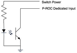
Dedicated opto switches consist of an IR transmitter and a IR phototransistor (receiver). The transmitter gets connected directly to power through a current limiting resistor (resistor value depends on the power level and the specific type of IR transmitter you use) so that it always transmits. The phototransistor works similarly to a mechanical switch except reversed. The circuit is pulled high on the P-ROC when not enough light is detected by the phototransistor (ie. when a ball is blocking the light) and driven low when the light is not blocked.

Connecting Matrixed Switches
The P-ROC supports switch matrixes up to 8x16. When in use, the matrix functionality automatically scans the matrix, capturing switch events on each switch in the matrix as they occur.
The topology of the matrix is 8 outputs (columns) and 16 inputs (rows). Refer to the P-ROC Board Specifications for a detailed listing of the connectors to use when wiring up your matrix. To use the full 8x16 matrix, you'll need to use the 0.156" pitch connectors. If you only need an 8x8 matrix, you can use either the 0.100" or 0.156" pitch connectors.
When the P-ROC is scanning the matrix, it will drive each matrix output low, one at a time, while capturing the states on each of the inputs. By iterating through each output, it can capture the states of each and every switch on the matrix in a very short amount of time, configurable down to 1 millisecond.
All switches on your matrix need to have a 1N4004 or equivalent diode in series with the switch. It doesn't matter which side of the switch the diode is on. Just make sure to orient the diode so the bar end points towards the P-ROC matrix output.
Mechanical Switches

Opto Switches
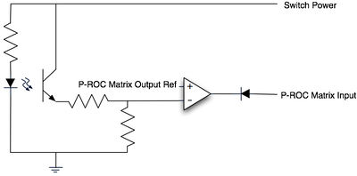
Unlike mechanical switches, which can be used on a matrix input in the same fashion as a dedicated input (with the addition of a diode), opto switches require some more circuitry. There are a few reasons for this, but the primary reason is that opto circuits are constantly active. In other words, the IR transmitter is constantly sending light, and the phototransistor is constantly trying to detect light. This means the output of the phototransistor is always active. Therefore, if it shares a P-ROC matrix input with other switches, it will corrupt the detected states of the other switches.
This issue is resolved, as shown in the diagram below, by adding a comparator circuit that compares the output of a phototransistor to a P-ROC matrix output reference. The P-ROC matrix output reference needs to be generated by even more circuitry (not shown) so that the phototransistors output is only relevant when the P-ROC matrix output is active. In other words, when the P-ROC matrix output is active (driven low), the phototransistor's output determines whether the P-ROC matrix input is driven low or pulled high. When the P-ROC matrix output is inactive, the phototransistor's output will result in the P-ROC matrix input being pulled high, regardless of the amount of light detected.

The P-ROC matrix output reference is commonly created with another comparator circuit that compares the P-ROC matrix output to a fixed voltage that's typically some percentage of the switch power.
Instead of wiring all of these comparator circuits for each and every opto you want to use on the switch matrix, it would be much simpler to use an existing opto board. A common opto board used in many existing pinball machines for the exact same purpose is:
A-15576 : 7-Opto Switch Board
This board is available from many pinball component suppliers and contains everything you should need except the IR transmitters and phototransistors, which incidentally are also available from most suppliers on PCBs and as standalone components (transmitters, receivers).
Burst Switches
< coming soon >
