OPP-Cypress
Contents
Open Pinball Project
The Open Pinball Project (OPP) was started in 2012 as a resource for pinball makers to have an inexpensive, fully open sourced project for controlling custom pinball machines. It is currently on a second generation design and has had a successful Kickstarter run of boards and components currently in the hands of makers all over the world.
Hardware
The OPP hardware is made up of three main components:
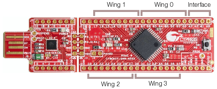
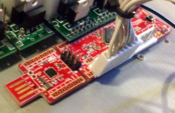
- The Processor board is a Cypress Semiconductor CY8CKIT-049-42XX PSoC prototyping board that can be purchased from Mouser or Digikey.
- The Interface board allows communications between Processor boards via a custom serial communications protocol.
- The Wing boards allow the control of solenoids, lamps, LEDs or input from switches.
Additionally, there is a Power Filter Board to allow the use of inexpensive switching power supplies.
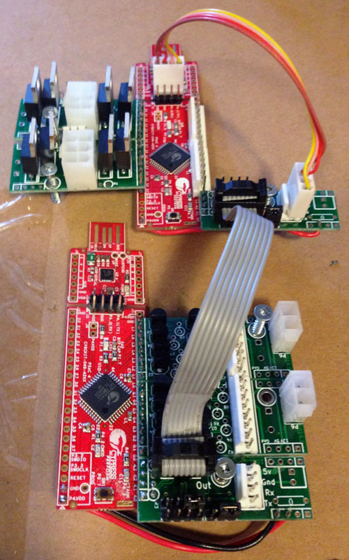
The following is an example of some fully assembled and wired OPP Processors with Wing boards.
Processor Boards
The Processor board can have up to four Wing boards controlling solenoids, incandescent lamps, or allowing input for switches. The Wing boards themselves can be combined in any configuration, so a single Processor board can support up to 16 solenoids (with 16 direct switch inputs), 32 switch inputs or 32 lamps. Each Wing board uses eight pins while the Interface board uses four.
All other pins are unused, except on the first board in the chain where the USB plug from the host controller is connected to the Interface board to provide power and serial connections for the other Processors in the chain.
The Processor itself does not run game rules or other game logic - a Controller like Mission Pinball running on a separate PC is still required to handle scoring and other game logic and to fire coils and light lamps as needed. The Processor simply provides the physical connection to playfield devices. (Coils can automatically be fired using the direct switch input for the coil to allow a "white wood" mode that does not require a controller).
Serial Chain
When needing to control more devices or have more switches than a single Processor board can handle, you can chain multiple Processors together via a Serial Chain using a series of 8-pin ribbon cables connected to IN and OUT connectors on the Interface wing.
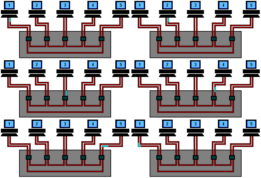
The ribbon cable serial link between boards works in a similar fashion to a Token Ring network, where each Processor receives messages via the serial line, looks for commands addressed to its ID, removes that command from the message and then passes the remaining message to the next Processor in the chain. The Processor then performs the requested action such as firing a solenoid or turning on a lamp. Switch events are passed back to the primary board and up to the host controller.
The following image gives a visual idea of how messages flow between the Processors:
Like in the above image, each Processor assigns itself an ID on power-up (starting with 0x20 and increasing with each additional Processor) based on its physical position in the serial chain. IDs are not saved between power cycles.
Note that inserting a new card in the middle of a chain will change the ID of every board after it. This will effect any hard-coded ID numbering in controllers like MPF, for example, but should not pose a big problem once the game is complete and no additional boards are added.
Interface Wing
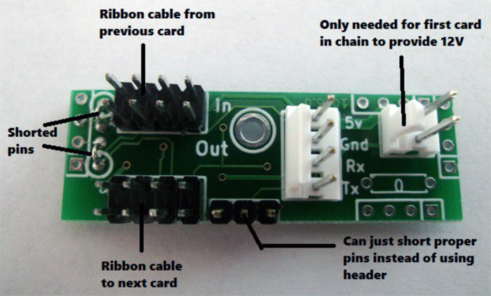
The Interface wing has no transistors or other electronic parts on it other than connectors. Its purpose is to distribute low voltage power (primarily 5V) and serial signals between each Processor board.
Note: The 12V connection is only necessary if using surface mount incandescent wing boards configured as high side switches. Normally the 12V connector can be left unpopulated.
Solenoid Wing
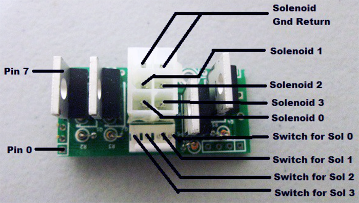
The Solenoid wing uses FQP13N06L MOSFETs to control up to four individual coils via a ground sink method, where the coils themselves are wired to the positive side of the high voltage power supply and the MOSFET provides a ground path when activated, firing the coil.
Standard coil voltages are 24V to 48V and upwards of 10A of current.
There are two connectors on the Solenoid wing - the larger 6-pin has four pins for the coil connections and two for ground. The 4-pin connector is for direct control switch inputs to control special solenoids.
Special Solenoids
For devices like flippers, slingshots or pop bumpers that require fast response to switch hits in order to fire coils, the Solenoid wing has four Direct Inputs that are used to directly activate the associated coil without the computer needing to detect a switch closure and send a solenoid activation command. These are known as Autofire coils.
As of this writing, OPP only supports Autofire coils using the direct inputs or switch inputs on the same controller as the solenoid itself. This means you can't have an Autofire switch on another controller.
Another advantage to using the direct switches is that it allows the game to be tested without a host controller, since pop bumpers, slingshots and flippers will work at power-on.
The 4-pin connector for the direct switches can cause some packaging issues with the solenoid connector, so it is recommended to leave it out when building the boards if there is no need for Autofire coils.
Incandescent Wing
The Incandescent wing uses 2N7000 MOSFETs to control up to eight direct wired incandescent lamps via the same ground sink method as the coils.
Lamps require a high current 6.3V power supply as each bulb needs about .25A at full brightness.
Direct wired means that each lamp is wired up and controlled individually via the 8-pin connector, rather than in the Matrix style that most commercial pinball machines used until recently.
The other 2-pin connector is for the Ground connection.
Switch Wing
Switches are wired directly to the Processor board via an 8-pin 2.54mm locking header.
Unlike the Solenoid and Incandescent wings, the Switch wing is set up as High-side, where the switch pins are at 5V and playfield and cabinet switches are tied to Ground, so that when a switch is activated, the pins are grounded and the switch is considered 'closed'. It is set up this way since the Processor pins have a Pull-Up resistor on them that is tied to 5V.
The switches provide a ground path for the normally-high inputs.
Power Filter Board
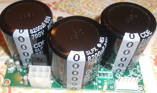
When firing solenoids, there is a large instantaneous draw of current from the power supply. A standard switching power supply may detect this as a short, and turn off. To prevent this from occurring, a large amount of bulk capacitance can be added, so the instantaneous current can be drawn from the bulk capacitors. Also, when initially charging the bulk capacitors, a large amount of current is drawn. A high power negative temperature coefficient (NTC) thermistor is used to reduce the initial current draw to charge the capacitors. This is the basis of the design for the Power Filter Board.
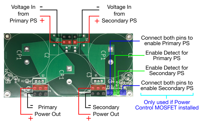
The board contains the following additional features:
- An LED to indicate when the capacitors are charged
- Ability to turn on/off the power by grounding a pin
- Output pin that can be used as an input to a processor for detecting if high voltage is enabled
- Board can be configured for one or two different high voltages through board population
The power filter board can be configured to provide bulk capacitance for one or two power supplies. If two power supplies are needed, a second P-Channel MOSFET and inrush current limiter must be bought.
If the ability to enable/disable the high power voltage isn't needed, a jumper can be added instead of the P-channel MOSFETs.
Before You Start
Prior to ordering and assembling the OPP boards, a number of tools and materials will need to be on hand, and a number of decisions will be made based on the pinball machine being built
Tools and Materials Required
To build and wire the OPP boards, you will need:
- Wire: Look on eBay for stranded wire in the 22-24AWG size.
- Side Cutters
- Pliers
- Soldering Iron: The Hakko FX888D is a popular, inexpensive brand. A lower-priced option is this iron from DX.
- Solder: Kester 44 is an excellent 63/37 solder. DX also has a less expensive option.
- Crimping Tool: Marco Specialities offers an inexpensive tool. Another option is the SN-28B ratcheting crimp tool - it can be purchased for less than $15 on eBay.
- Pin Extractor: Digikey has the Molex-branded tool for extracting the Mini-Fit Jr. style of square connectors used on the Solenoid wings.
Determine Board Layout
Prior to purchasing the OPP boards and components, you need to know how many solenoids, lamps and switches you need to support, where to put them, and how they will be mounted.
For example, a custom game might require 31 inputs, 10 solenoids (with 10 direct inputs), and 43 incandescent bulbs. This could be accomplished with four Processor boards and four Interface wings, three Solenoid wings, six Incandescent wings and five Switch wings. Technically this is more boards and wings than are strictly required, as the Processor boards could handle a denser wing configuration, but this layout cuts down on the total wiring required by placing Processors close to the devices they are controlling, saving significant time and materials.
Alternatively, consider a Williams Jokerz machine. It has 19 solenoids (including direct inputs), 39 switches and 63 incandescent bulbs (which includes 9 flashers). A possible layout for that is five Processor boards with five Interface wings, four Solenoid wings, eight Incandescent wings and five Switch wings.
You can place Processors near what is being controlled, or put them all together in the head of the machine like a traditional commercial pinball - it is entirely up to the maker as to where to place Processors, but placement will determine the final number of Processors and wings required.
Once the total number of Processor and Wing boards has been determined, and their approximate location in the final machine, parts can be ordered.
Power Supply Needs
When running solenoids and lamps, you'll need three voltages: 5V 3A for logic, 6.3V 10A for lamps and 24V to 48V 10A for solenoids (depending on what coils you use). See the Power Supply section for details of what is available.
An inexpensive option is to use a PC power supply, which provides high current 5V for logic and 12V for lamps. A high power DC-DC step down Buck Converter can be used to convert 12V to 6.3V for incandescents.
You can use a separate 24V to 48V 10A switcher for solenoids if you also use the Power Filter Board.

